| C H A P T E R 3 |
|
Hardware Installation |
This chapter describes some of the typical system configurations in which the Netra CP2160 board may be used.
This chapter contains the following sections:
Refer to the Important Safety Information for Sun Hardware Systems (816-7190-xx) for general safety information.
Read these safety statements specific to the Netra CP2160 board carefully before you install or remove any part of the system.
The installer must be familiar with commonly-accepted procedures for integrating electronic systems and with the general practice of Sun systems integration and administration. Although parts of these systems are designed for hot-swap operation, other components must not be subjected to such stresses. Work with power connected to a chassis only when necessary and follow these installation procedures to avoid equipment damage.
This equipment is sensitive to damage from electrostatic discharge (ESD) from clothing and other materials. Use the following antistatic measures during an installation.
The other end of the strap lead should be connected to one of the following:
Read the following subsections before starting to install these boards. In addition, do the following:
1. Become familiar with the contents of the referenced documentation.
2. Verify that all listed hardware and software is available (see Section 1.4, System Requirements).
3. Check power, thermal, environmental and space requirements (see Section 3.2.1, Checking Power, Thermal, Environmental, and Space Requirements).
4. Verify that local area networking (LAN) preparations are completed (see Section 3.2.2, Determining Local Network IP Addresses and Hostnames).
5. Ensure that the hostnames and their network IP addresses are allocated and registered at the site.
Collect the following information to connect hosts to the local area network (LAN). Ask your network administrator for help, if necessary. This information is not needed for a standalone installation You can use TABLE 3-1 to record this information.
|
IP addresses[1] and hostname for each Netra CP2160 client |
|
|
Type of name service and corresponding name server names and IP addresses--for example DNS and NIS (or NIS+) |
|
You may need the MAC (Ethernet) addresses of the local hosts to make nameserver database entries. The MAC address can be seen in the console output while booting to the ok prompt. It can also be derived from the Host ID seen on the label of the I2C EEPROM package.
The steps in this section summarize the Netra CP2160 board installation at a high level. Make sure to read the details in Section 3.3, Configuring the Netra Board Hardware through Section 3.7, Software Installation before installing the board.
The procedure to setup and configure a Netra CP2160 board in a system includes the following steps:
1. Configure host board physical hardware. For example, install memory and PMC cards, replace the serial EEPROM, and set switches if necessary.
2. Configure the transition card with PIMs, switch settings, or connector attachments, as necessary.
3. Physically install the transition card (as necessary), host, and any peripheral boards into the chassis.
4. Connect the host(s) to a local network. Alternatively, the host can be run as a standalone system without a network connection.
5. Install the operating system.
This section lists hardware installation and settings that may or may not apply for your board configuration. Read and perform the procedures, as necessary, before installing the Netra CP2160 board into the chassis.
The Netra CP2160 board can accommodate modular memory. For directions on the installation process of the memory modules on the Netra CP2160 board, refer to the document Memory Module Installation and Removal Guide for Netra CP2000/CP2100 Series Boards (817-0654-xx).
Use the PMC card manufacturer's procedure to install these cards.
Section B.4, Switch Settings details the SW2501 and SW4101 switch settings for the Netra CP2160 board.
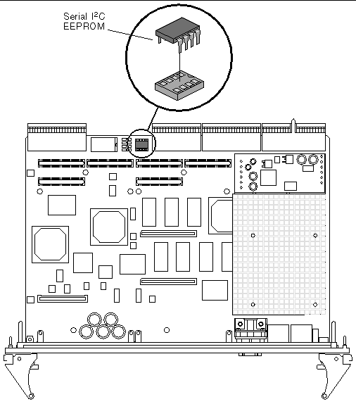
FIGURE 3-1 Replacing the Serial I 2 C EEPROM

The serial I2C EEPROM stores the backup copy of the board MAC address and host ID information (see Section 5.3.4.4, Serial I2C EEPROM for more information).
If you need to replace the Netra CP2160 board, remove the serial I2C EEPROM from the original board and install it on the new Netra CP2160 board.FIGURE 3-1 shows the position of the serial I2C EEPROM on the Netra CP2160 board.The MAC address label is positioned on top of both the serial I2C EEPROM and the J3 connector. See FIGURE 1-6 for the location of the MAC address label.
If you are using the XCP2060-TRN I/O transition card, refer to the XCP2060-TRN I/O Transition Card Manual for Netra CP2060/CP2080/CP2160 CompactPCI Boards (P/N 806-6203-xx). You may also refer to the transition card manual for detailed connector pin assignments.
Use the PMC card manufacturer's procedure to install these cards. Only the PIM A and PIM B Connector Power Pin Assignments are provided in TABLE 3-2.


This section describes the installation of the transition card, the system host board, the satellite board and the I/O cards into a Netra CP2160 CompactPCI system chassis.
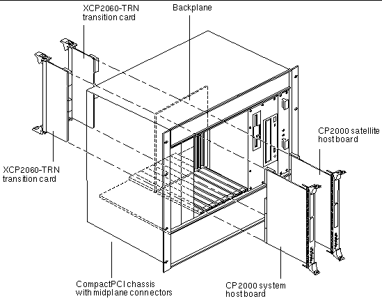
Use the installation procedure detailed in the XCP2060-TRN I/O Transition Card Manual for Netra CP2060/CP2080/CP2160 CompactPCI Boards (806-6203-xx) to install the XCP2060-TRN transition card.
|
Note - If the system power is on when installing the XCP2060-TRN I/O transition card, the transition card must be installed before its mating Netra CP2160 board. |
A compatible transition card must be used with the Netra CP2160 board for rear I/O access. The transition card enables access to the network, to a boot device and to a console terminal. You may use the XCP2060-TRN I/O transition card, or you may design your own transition card.
FIGURE 3-2 Installing the XCP2060-TRN CPCI I/O Transition Card

A CompactPCI chassis contains:
To use the Netra CP2160 board as a system controller, install the board into the system board slot. To use the Netra CP2160 board as a satellite board, install the board into a peripheral slot. (see Section 5.4.3.1, Arbitration in System Controller Role).
1. Ensure that power is disconnected from the chassis.
The Netra CP2160 satellite board can be installed while the chassis is powered--however only start with a powered chassis if necessary. See Section 2.1, Hot-Swapping a Netra CP2160 Satellite Board for information on hot-swapping the Netra CP2160 satellite board.
The Netra CP2160 board cannot be hot-swapped when used as a system controller.
2. Check that the corresponding XCP2060-TRN I/O transition card is installed.
If you need a transition card for I/O for the Netra board, ensure that it is already present in the chassis. This step is essential if the chassis is powered during the installation.
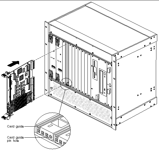
3. Slide the Netra CP2160 board into the appropriate slot on the corresponding top and bottom mounting rails and toward the backplane while gently pushing the board handles inward.
While sliding the board, ensure that the Netra CP2160 board extraction levers are aligned perpendicular to the card flange in the unlocked position and that the board connectors are aligned with the transition card connectors.
4. Install two screws through the top and bottom of the front connector plate to secure the board.
FIGURE 3-3 Installing a Typical Netra CP2160 Board Into a CompactPCI Chassis in a System Host Slot

|
Note - Follow the CompactPCI chassis manufacturer's instructions to make sure the Netra CP2160 board is installed into the system controller slot. |
Various I/O boards (I/O cards) can be installed in the chassis that contain the Netra board. If these boards meet hot-swap requirements, these can be hot-inserted and do not require that the system is powered down. These I/O cards need to be installed in their respective slots. Refer to the chassis manufacturer's documentation for slot assignments and for special installation instructions.
The basic I/O card installation procedure is the same as described in Section 3.4.2, Installing the Netra CP2160 Board. The ejector handles on the I/O cards may not be the same style as Netra board ejector handles. Some boards have retracting ejector handles. Refer to the I/O card manufacturer's instructions on how to engage or disengage ejector handles that secure that board to the chassis.
Refer to Section 2.2, Peripheral I/O Board Configuration for information on configuring and I/O card to work with a Netra CP2160 host board.
This section describes how to set up a computer that contains the Netra CP2160 board.
1. Using a category 5 grade network cable, connect one RJ45 connector into the receptacle on the front panel of the Netra CP2160 board or on the rear flange of the transition card (RTM).
The other end must be connected to a suitable 10/100 Mb Ethernet hub on the local subnet. To use the front ethernet ports, set the NVRAM variable to true (this is the default setting). To use the RTM ethernet port, set the NVRAM variable "front-phy?" to false. The command syntax at the ok prompt is:
ok setenv front-phy? false
ok reset-all
Plug the ethernet cables only on one set of ports; plug the cables on the front panel ports when using front ports and plug them on the RTM when using the the rear ethernet ports. They should not be plugged on both sides at the same time.
2. Connect I/O cabling to the host board and to the serial port of the host system.
3. Connect a serial cable to the ttya port on the front panel of the Netra CP2160 board or the the XCP2060-TRN CPCI I/O transition card of the target machine and to the serial port of the host machine.
4. Use the tip utility on the host system to establish a full-duplex terminal connection with the Netra CP2160 board.
5. At the UNIX prompt in a command tool or shell tool, type:
tip -9600 /dev/ttya
6. Connect any other peripheral devices (such as a printer) to the appropriate connector.
1. Power on the system that contains the Netra CP2160 board to run the power-on self-tests (POST). For details on POST, see Chapter 4, Firmware.
2. After running POST, install the Solaris operating environment package on the system that contains the Netra CP2160 board (see Section 3.7.1, Installing the Operating System).
If the installed version is not current, update the OpenBoot PROM before continuing (see Section 3.6.3, Upgrading the OpenBoot PROM Firmware). The third character group (X) in OpenBoot PROM is the revision number.
To determine the installed OpenBoot PROM version, use the .version command at the ok prompt. An example of the screen print-out is shown below.
|
Note - In the above printout example, the OBP release version is 4.0.11, as specified in the seventh line of the printout. |
Use the prtconf command at the machine_name% prompt.
This firmware can only be upgraded when operating at the OpenBoot PROM level, that is, at the ok prompt.
|
Note - See information for sequencing of SMC and board upgrade information provided on the product web site at:
|
1. Download the latest Netra CP2160 host firmware binaries.
2. Bring the system down to OpenBoot PROM level.
If your Netra CP2160 board is currently running Solaris software, become superuser and issue the command:
3. Check the present firmware revision.
Check the current firmware revision on the target system by typing:
|
Note - In the above printout example, the OBP release version is 4.0.11, as specified in the seventh line of the printout. |
4. Disable autoboot, then reset the system.
Disable autoboot and reset the system by means of the commands:
5. Flash update your firmware.
ok flash-update device; obp-file-path/obp-latest-binary ok smc-flash-update device; smc-file-path/smc-latest-binary |
The system should automatically reset. If it does not, power cycle it.
6. Check the firmware revision.
Check the firmware revision by typing:
The form of the output appears as in Step 3. Ensure that the version information shows up as expected. If not, please attempt the OpenBoot PROM upgrade once more.
7. Enable auto booting and reset the system.
a. Enable auto booting by typing:
b. Reset the system to boot Solaris software:
Please contact your service personnel if you face any problems.
|
Note - Solaris scripts are also available to upgrade core OpenBoot PROM firmware. |
The Solaris 8 operating environment, Release 2/02 or subsequent compatible version, may be used with the Netra CP2160 board system. Refer to Solaris installation manuals for the installation procedure (see Appendix D).
For additional software functionality available through the CP2000 Supplemental CD 4.0 for Solaris 8, contact your field application engineer or refer to the product web site at:
http://www.sun.com/products-n-solutions/nep/hardware/boards/cp2160/
|
Note - CP2000 Supplemental CD 3.1 for Solaris 8 can also be used with the Netra CP2160 board, but does not provide all of the features available in the CD 4.0 version. |
Sun Validation Test Suite (SunVTSTM) is a comprehensive software package that tests and validates the Netra CP2160 board by verifying the configuration and function of most hardware controllers and devices on the board. SunVTS is used to validate a system during development, production, inspection, troubleshooting, periodic maintenance and system or subsystem stressing. SunVTS can be tailored to run on various types of machines ranging from desktops to servers with modifiable test instances and processor affinity features.
You can perform high-level system testing by using the appropriate version of SunVTS. For detailed information on SunVTS support and downloads, refer to the following web site:
http://www.sun.com/oem/products/vts/index.html
The SunVTS packages are also located on the Solaris 8 Supplemental Software CD for Sun Computer Systems that ships with the Solaris operating environment release.
Ensure that the SunVTS software version is compatible with the Solaris operating environment version being used. Solaris 8 2/02 operating environment is compatible with SunVTS 4.6 package.
Information on the version of the SunVTS software installed can be found in the file:
To obtain SunVTS documentation, contact your local customer service representative or field application engineer.
|
Note - For security reasons only a superuser is permitted to run SunVTS. Installation and starting instructions are included with the software when it is downloaded. |
Copyright © 2004, Sun Microsystems, Inc. All Rights Reserved.