| A P P E N D I X A |
|
Specifications |
Specifications for the Netra CP2160 board are provided in the following sections:
|
CompactPCI J4 is unconnected at the board; which enables this board to be used in H110 chassis |
|
The CPCI standard, PICMG 2.0 Rev 3, calls out the maximum component heights of 13.71 +/- 0.03 mm. Due to variations in parts, board flatness, board thickness, and manufacturing tolerances, the memory turrets installed on a Netra CP2160 board may exceed this limit.
PICMG 2.0 Rev 3 and IEEE 1101.10-1996 requires 2.54mm between the top of components and the separation plane, and there is at least approximately 0.5mm to 2mm of clearance to solder-side components or leads of an adjacent board from that same separation plane. Therefore, there is very little chance that a small specification violation will impact an adjacent card in a PICMG 2.0 Rev 3 compliant chassis.
Care should be taken when installing the boards in systems that have extreme solder-side component heights or in system chassis that don't allow clearances specified in the PICMG or IEEE standards.
The Netra CP2160 board also has a solder side cover installed. The components on the solder side cover meet the limits of the CPCI specification for maximum height. The solder side cover is nominally 1mm thick. When this cover rests upon components greater than 1mm in height, the cover itself may violate the CPCI specification where it rests on these components.
|
1 GB on-board memory, with an additional 1 GB double-wide memory available for order |
|
|
One custom 198-pin stackable module; see TABLE A-4 for allowable combinations |
|
|
3.3V, synchronous DRAM with ECC LVTTL-compatible CMOS; configured on bus width of 64-bit + 8-ECC bits |
|
|
Serial EEPROM provides serial presence detect (SPD) to IPMI interface |
|
|
8-bit; single bit error correction; double-bit error detection |
The default memory configuration on the Netra CP2160 board is 1 GB. The possible memory configurations are shown on TABLE A-4.
For directions on the installation process of the stackable memory modules on the Netra CP2160 board, refer to the document Memory Module Installation and Removal Guide for Netra CP2000/CP2100 Series CompactPCI Boards (817-0654-xx).
|
J21, J22 carry PCI signals; J24 module I/O is connected to CPCI backplane J5; J23[1] |
|
|
J11, J12 carry PCI signals; J14 module I/O is connected to CPCI backplane J3 |
|
|
Max power load -- per module, combined power rails (5V, 3.3V,
|
The PMC standard, IEEE 1386, calls out the maximum component height of 4.70 mm below a PMC card. This allows for a 0.6 mm gap separating components on the motherboard from components on the PMC card. The Netra CP2160 board utilizes a standard memory connector that is nominally 5.2mm tall. This means that there would be only 0.1 mm of clearance in two areas below the PMC slot closest to the CPU (PMC B )in the area of two motherboard memory sockets of 4.93 mm by 43.40 mm.
The PMC A slot is not affected by the memory socket height. When at all possible, install any PMC cards that barely meet or exceed PMC component height restrictions in the PMC A slot. PMC disk drive cards in particular may impact the memory connectors on PMC B, as some commercially available PMC disk cards meet or exceed component height restrictions.
This section provides information on power sequencing and power requirements by connection phase.
TABLE A-6 shows the power drawn from the backplane connector by phase.
|
Early power on long pins[2] |
Main power on medium pins:[3] |
(with 2GB total memory)[4] |
||
|---|---|---|---|---|
|
+5V[5] |
||||
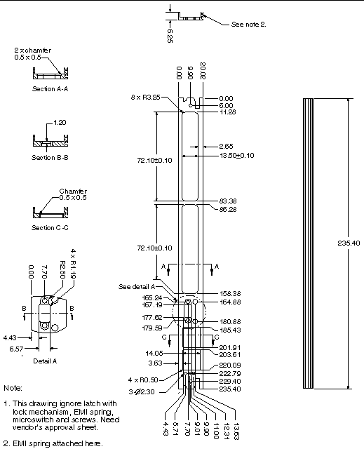
These products comply with the mechanical specifications to be found in the CompactPCI specification PICMG 2.0 R3.0. See Appendix D for a reference to this specification.
FIGURE A-1 shows a mechanical illustration of the Netra CP2160 board panel.
FIGURE A-1 Mechanical Illustration of the Netra CP2160 Board Front Panel

|
Low Limit[6] |
||
|---|---|---|
|
5% RH[7] |
||
|
As stated in NEBS GR-63 CORE specifications, section 4.3.1 and 4.3.2 for shock criteria and 4.4.3 for vibration criteria; |
||
The ASM CPU sensor should not exceed 850 C when installed in the system. Refer to the Netra CP2000 and CP2100 Series CompactPCI Boards Programming Guide
(816-2485-xx) for more information on ASM thermal validation.
Reliability prediction is the first measurement point of expected behavior of the inherent design mean time between failures (MTBF) of the product. MTBF values calculated are shown in TABLE A-8.
|
Rate (AFR in %)[8] |
||
|---|---|---|
|
Netra CP2160 board[9] |
||
All printed wiring boards (PWBs) are manufactured by UL recognized manufacturers, and have a flammability rating of 94-V0 or better.
Compliance with EMI and safety regulations for products including the Netra CP2160 board is entirely the responsibility of OEMs. The Netra CP2140 board has passed FCC Class B tests in representative enclosures. However, the EMI Class of the end use system is dependent upon system level EMI design parameters.
The Netra CP2160 boards are intended to be incorporated into systems meeting the following regulations and compliances:
Board requirements for NEBS Level 3 criteria provide the highest assurance of product operability with minimal service interruptions over the life of the equipment. The requirements include the following categories and all associated sections and subcategories:
Copyright © 2004, Sun Microsystems, Inc. All Rights Reserved.