| C H A P T E R 1 |
|
Overview of the Netra CP2160 CompactPCI Board |
The Netra CP2160 CompactPCI board is a crucial building block that network equipment providers (NEPs) and carriers can use when scaling and improving the availability of next-generation, carrier-grade systems. Based on industry standards, the Netra CP2160 board provides high performance and is easily customized for satellite processing. Powered by a 650 MHz UltraSPARC IIi processor, the board is also capable of host processing.
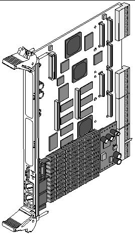
The Netra CP2160 board enables customers to mix and match third-party PCI mezzanine cards (PMCs), making it easier for them to tailor solutions to their specific application needs. The Netra CP2160 boardprovides PCI Industrial Computers Manufacturers' Group (PICMG) CompactPCI compliance (for details, see TABLE 1-1) and are NEBs Level 3 certified to meet the CompactPCI system requirements of the communications and service provider environments. An example of a typical Netra CP2160 board is illustrated in FIGURE 1-1.
This chapter contains the following sections:
The Netra CP2160 board is a CompactPCI single-board computer designed for high-performance embedded, compute density applications. Powered by a 650 MHz UltraSPARC IIi processor, with full utilization of the PMC slots, the Netra CP2160 board has System Management Controller (SMC) capability that suppports hot-swap operations, system managment, and environmental monitoring. The Netra CP2160 board is an ideal platform for NEPs to use for a wide variety of Solaris applications.
An illustration of the board is shown in FIGURE 1-1. A summary of features of the Netra CP2160 board is given in TABLE 1-1.
FIGURE 1-1 Netra CP2160 System Host Board or Satellite Board
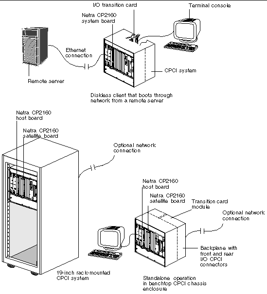
The Netra CP2160 boards can be mounted in various enclosures, such as shown in FIGURE 1-2. The boards can be deployed in various electrical configurations to suit each end-user requirement. For example, the host board can be configured to boot from a network as a diskless client with either a front or rear network connection. Alternatively, industry-standard PMC and PIM hardware from Independent Hardware Vendors (IHVs) can be installed to provide local disk I/O, which may optionally be used as a boot path. The installation procedure is independent of the type of enclosure, whether a floor-mounting rack or a bench-top cabinet is used. The Netra CP2160 board has fixed on-board memory and additional memory can also be installed.
FIGURE 1-2 Examples of Netra CP2160 Board Mounting Configurations
Systems that conform to CompactPCI specifications require differentiation of chassis board slots, depending upon the function of the board.
To function as a system host board, a Netra CP2160 board has connections that distribute PCI clocks and receive interrupts from peripherals. The board must be installed in a system slot in the CompactPCI segment, because only the system chassis slots have backplane wiring with the full set of connections required to enable the system host board function. The Netra CP2160 board can control CompactPCI peripheral hardware if it is installed as a system controller in a PICMG system slot, because it detects a special enable signal (SYS-EN signal) in this slot. A system host slot is marked with an open triangle legend, as specified in CompactPCI Specification, PICMG 2.0 R3.0 (see Appendix C for reference details).
The Netra CP2160 board can be placed in one of the remaining (nonsystem controller) slots if the user wants to use it as a functional satellite board.
For a definition of the system host board and satellite board see the Glossary in this book.
The Netra CP2160 board has two Ethernet ports and one serial port on the front panel. The addition of IHV-built PMC modules provide additional I/O to the front panels. PMC modules decode their custom I/O from the Netra board's on-board PCI bus B signals. See Section 5.4.4, PMC and PIM Interface for further information.
The optional XCP2060-TRN transition card from Sun Microsystems installs into the rear of the CompactPCI enclosure, opposite the Netra CP2160 board (see FIGURE 1-3). The transition card connects with the host CompactPCI P3 and P5 connectors through the backplane pins and carries two serial ports and a USB port out to its rear-panel flange.
FIGURE 1-3 XCP2060-TRN Transition Card with Location of On-Board Components
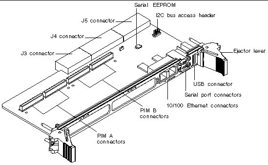
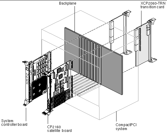
FIGURE 1-4 and FIGURE 1-5 show the physical relationship between host boards, transition cards, and the backplane in a typical system.
The transition card can also be fitted with IHV PCI Interface Modules (PIMs) which are configured to bring I/O channels to the unit rear panel. A PIM hardware kit includes a card for the PMC slot and a card for the PIM slot on the transition card. A PIM is a rear-panel extension added to a PMC module. When the PIM I/O is configured, the front PMC I/O output is not accessible.
The customer can order the XCP2060-TRN transition card, build a custom card, or buy from an Independent Hardware Vendor (IHV). A minimal set of I/O must provide for a boot path for the host board and for a path for console I/O to deliver commands and to read board and system status.
Possible boot and console configurations are described in TABLE 1-2. Sun Microsystems provides the host boards and a compatible XCP2060-TRN transition card for Netra CP2160 boards. This transition card brings out 10/100 Ethernet RJ45 ports from the host to the rear of the system, which can be used to accomplish network boot as a diskless client. The other configurations require IHV hardware.
|
Ethernet[1] |
XCP2060 I/O transition card--supplied as an option for rear access; Ethernet also available on front panel with no extra hardware required |
Default boot path uses Ethernet port on transition card; host runs in diskless client configuration. |
|
May be used for local boot; requires optional transition card with PMC SCSI I/O. |
||
|
Serial port A on optional transition card is path of default console I/O (see FIGURE 1-3 for location). |
||
|
XCP2060-TRN I/O transition card and PMC video graphics controller, or CPCI video controller card |
CPCI card video controller takes one CPCI slot and attaches directly to CPCI backplane. |
|
FIGURE 1-4 Typical CPCI System Illustrating the Netra CP2160 Board in System Board Role With XCP2060-TRN Transition Card
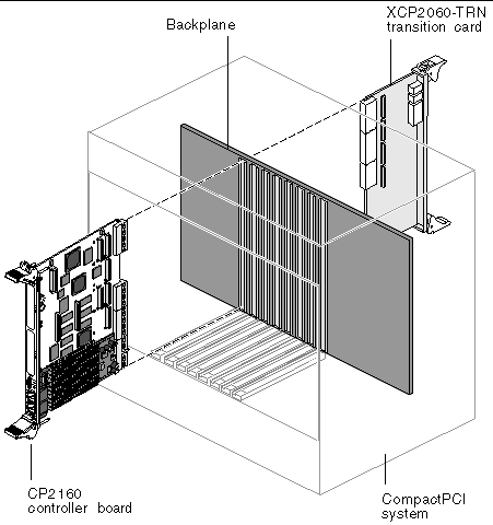
FIGURE 1-5 Typical CPCI System Illustrating the Netra CP2160 Board in Satellite Board Role With XCP2060-TRN Transition Card
This section briefly discusses the hot-swap support on the Netra CP2160 boards.
Instructions on hot-swap configurations for the Netra CP2160 satellite board are in Section 2.1, Hot-Swapping a Netra CP2160 Satellite Board.
See Appendix C for a reference to the PICMG CompactPCI Hot Swap Specification which provides a detailed description of this subject. In general, the hot-swap process includes the orderly connection of the hardware and software. This process uses:
There are three models of hot swap described in the PICMG CompactPCI Hot Swap Specification: basic hot-swap, full hot-swap, and HA hot-swap.
TABLE 1-3 lists the hot-swap support details when a Netra CP2160 board functions as a system host board or as a satellite board.
|
Yes[2] |
|
Note - The Netra CP2160 host board supports satellite hot-swap insertion/extraction, but the host board itself cannot be inserted or extracted while the server is powered-on. See Section 2.1, Hot-Swapping a Netra CP2160 Satellite Board for more information. |
Sun provides these items to customer order:
This memory card is optional must be ordered separately from the Netra CP2160 board. See TABLE A-4 for more information on board memory configurations.
A compatible transition card provides rear I/O access with the Netra CP2160 board. The transition card enables rear system access to the network, to a boot device, and to a console terminal (shown in FIGURE 1-3).
This transition card is optional and must be ordered separately from the Netra CP2160 board. See the XCP2060-TRN I/O Transition Card Manual for Netra CP2060/CP2080/CP2160 CompactPCI Boards (806-6203-xx) referenced in Appendix C.
The customer must procure the following components as required:
See Section B.2, Front Panel Connectors and XCP2060-TRN I/O Transition Card Manual for Netra CP2060/CP2080/CP2160 CompactPCI Boards (806-6203-xx )for descriptions of I/O connections.
|
CompactPCI system box for 6U boards (includes chassis, backplane, power supply[3])[4] |
||
The Solaris 8 operating environment, release 2/02, or subsequent compatible version, may be used with the Netra CP2160 board system. Refer to Solaris installation manuals for the installation procedure (see Appendix C).
For additional software functionality available through the CP2000 Supplemental CD 4.0 for Solaris 8 contact your field application engineer or refer to the product web site at:
http://www.sun.com/products-n-solutions/nep/hardware/boards/cp2160/
|
Note - CP2000 Supplemental CD 3.1 for Solaris 8 can also be used with the Netra CP2160 board, but does not provide all of the features available in the 4.0 version. |
Should you have any technical questions or support issues that are not addressed in the Netra CP2160 board documentation set or on the Web site contact your local Sun Enterprise Services. This hardware carries a 1-year return-to-depot warranty. For customers in the US or Canada, please call 1-800-USA-4SUN (1-800-872-4786). For customers in the rest of the world, find the World Wide Solution Center nearest you by visiting our web site:
http://www.sun.com/service/contacting/solution.html
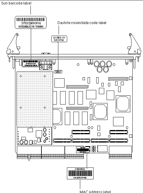
When you call Sun Enterprise Services, be sure to indicate that the Netra CP2160 board was purchased separately and is not associated with a system. Please have the board identification information ready. For proper identification of the board be prepared to give the representative the board part number, serial number, and date code (see FIGURE 1-6).
The Netra CP2160 board part number, serial number, and version can be found on stickers located on the card (see FIGURE 1-6). For proper identification of the board, please see the list below along with FIGURE 1-6.
The Sun barcode label provides the following information (see FIGURE 1-6):
The Dash/Revision/Date Code label provides the following information (see FIGURE 1-6):
The MAC address label contains the MAC address for the board in printed and barcode form. See Section 3.3.4, Replacing the Serial EEPROM for information on installation and removal of the MAC address label.
FIGURE 1-6 Labeling on a Typical Netra CP2160 Board
Copyright © 2004, Sun Microsystems, Inc. All Rights Reserved.