| C H A P T E R 8 |
|
Troubleshooting Your Array |
This chapter covers the following troubleshooting topics:
To check front-panel and back-panel LEDs, see Checking LEDs.
For more troubleshooting tips, refer to the Sun StorEdge 3310 SCSI Release Notes at:
http://www.sun.com/products-n-solutions/hardware/docs/Network_Storage_Solutions/Workgroup/3310
By default, all RAID arrays are preconfigured with one or two logical drives. For a logical drive to be visible to the host server, its partitions must be mapped to host LUNs. (For mapping details, refer to Mapping Logical Drive Partitions to Host LUNs.) Check that you have completed this task.
To make the mapped LUNs visible to a specific host, perform the steps required for your operating system or environment, if there are any special requirements. For host-specific information about different operating environments and operating systems see:
If you attach a JBOD array directly to a host server and do not see the drives on the host server, check that the cabling is correct and that there is proper termination. Refer to the special cabling procedures in Cabling JBODs.
For additional information about specific servers, see the operating system appendices in the previous section of this document.
Controller failure symptoms are as follows:
A "SCSI Bus Reset Issued" alert message is displayed for each of the SCSI channels. A "Redundant Controller Failure Detected" alert message is also displayed. These messages are also written to the event log.
If one controller in the redundant controller configuration fails, the surviving controller temporarily takes over for the failed controller until it is replaced.
A failed controller is managed by the surviving controller which disables and disconnects from its counterpart while gaining access to all the signal paths. The surviving controller then manages the ensuing event notifications and takes over all processes. It is always the primary controller regardless of its original status, and any replacement controller afterward assumes the role of the secondary controller.
The failover and failback processes are completely transparent to the host.
Controllers are hot-swappable if you are using a redundant configuration, and replacing a failed unit takes only a few minutes. Since the I/O connections are on the controllers, you may experience some unavailability between the times when the failed controller is removed and a new one is installed in its place.
To maintain your redundant controller configuration, replace the failed controller as soon as possible. For details, refer to Sun StorEdge 3000 Family FRU Installation Guide.
This section describes automatic and manual procedures for rebuilding logical drives.
|
Note - As disks fail and are replaced the rebuild process regenerates the data and parity information that was on the failed disk. However, the NVRAM configuration file that was present on the disk is not recreated. After the rebuild process is complete, restore your configuration as described in Restoring Your Configuration (NVRAM) From a File. |
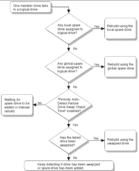
Rebuild with Spare: When a member drive in a logical drive fails, the controller first examines whether there is a local spare drive assigned to this logical drive. If yes, it automatically starts to rebuild the data of the failed disk to it.
If there is no local spare available, the controller searches for a global spare. If there is a global spare, it automatically uses it to rebuild the logical drive.
Failed Drive Swap Detect: If neither a local spare drive nor a global spare drive is available, and the "Periodic Auto-Detect Failure Drive Swap Check Time" is "disabled," the controller does not attempt to rebuild unless you apply a forced-manual rebuild.
To enable this feature, follow these steps:
1. Choose "view and edit Configuration parameters  Drive-side SCSI Parameters
  Periodic Auto-Detect Failure Drive Swap Check Time."
When the "Periodic Auto-Detect Failure Drive Swap Check Time" is "Enabled" (that is, a check time interval has been selected), the controller detects whether or not the failed drive has been swapped (by checking the failed drive's channel/ID). Once the failed drive has been swapped, the rebuild begins immediately.
|
Note - This feature requires system resources and can impact performance. |
2. Choose a time interval from the displayed list to enable this feature, or choose Disabled to disable it.
A confirmation dialog is displayed.
If the failed drive is not swapped but a local spare is added to the logical drive, the rebuild begins with the spare.
For a flowchart of automatic rebuild, see FIGURE 8-1.
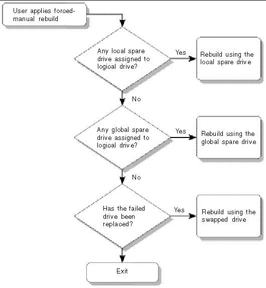
When a user applies forced-manual rebuild, the controller first examines whether there is any local spare assigned to the logical drive. If yes, it automatically starts to rebuild.
If there is no local spare available, the controller searches for a global spare. If there is a global spare, the logical drive rebuild begins. See FIGURE 8-2 for a flow-chart illustration of this process.
If neither local spare nor global spare is available, the controller examines the SCSI channel and ID of the failed drive. After the failed drive has been replaced by a healthy one, the logical drive rebuild begins on the new drive. If there is no drive available for rebuilding, the controller does not attempt to rebuild until the user applies another forced-manual rebuild.
RAID 1+0 allows multiple-drive failure and concurrent multiple-drive rebuild. Drives newly swapped must be scanned and set as local spares. These drives are rebuilt at the same time; you do not need to repeat the rebuilding process for each drive.
If there is a failed drive in the RAID 5 logical drive, replace the failed drive with a new drive to keep the logical drive working.
|
Note - The following procedure only works if there is no I/O activity. |
To find a failed drive, identify a single drive, or test all drive activity LEDs, perform the following steps.
1. Choose "view and edit scsi Drives."
2. Select any drive and press Return.
3. Choose "Identify scsi drive  flash All drives."
This command flashes the activity LEDs of all of the drives in the drive channel.
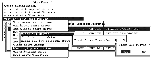
The option to change the Flash Drive Time is displayed.
4. Press Return to accept the default value, or type a flash time between 1 and 999 seconds and press Return.
A confirmation dialog is displayed.
The read/write LED of a failed hard drive does not light. Identifying the drive whose LED does not light helps you avoid removing the wrong drive.
Alternatively, to flash the read/write LED of only a selected drive, choose "flash Selected drive" or "flash all But selected drive" and perform the same procedure.
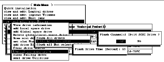
When you choose this menu option, the read/write LED of the drive you select flashes for a configurable period of time from 1 to 999 seconds.
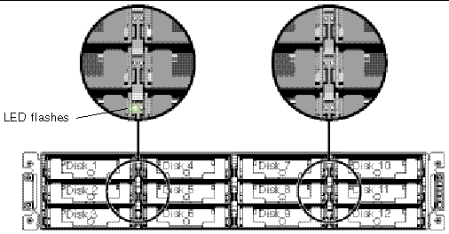
The "Flash All SCSI Drives" menu option flashes LEDs of all good drives but does not flash LEDs for any defective drives. In the illustration, there are no defective drives.
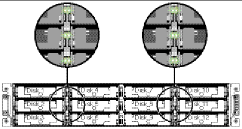
With this menu option, the read/write LEDs of all connected drives except the selected drive flash for a configurable period of time from 1 to 999 seconds.
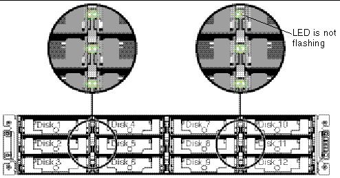
With the redundant RAID array system, your system is protected with the RAID parity drive and by a default global spare or spares.
In an extremely rare occurrence where two or more drives appear to fail at the same time, perform the following steps.
1. Discontinue all input/output activity immediately.
2. To cancel the beeping alarm, in the firmware Main Menu, choose "system Functions  Mute beeper. "
See Silencing Audible Alarms for more information about silencing audible alarms.
3. Physically check that all the drives are firmly seated in the array and that none have been partially or completely removed.
4. Check again the firmware Main Menu and check the "view and edit Logical drives," and look for:
Status: FAILED DRV (one failed drive) or
Status: FATAL FAIL (two or more failed drives)
5. Highlight the logical drive, press Return, and select "view scsi drives."
If two physical drives have a problem, one drive has a BAD status and one drive has a MISSING status. The MISSING status is a reminder that one of the drives may be a "false" failure. The status does not tell you which drive might be a false failure.
7. Repeat steps 4 and 5 to check the logical and SCSI drive status.
After resetting the controller, if there is a false bad drive, the array automatically starts rebuilding the failed RAID set.
If the array does not automatically start rebuilding the RAID set, check the status under "view and edit Logical drives."
|
Note - As disks fail and are replaced the rebuild process regenerates the data and parity information that was on the failed disk. However, the NVRAM configuration file that was present on the disk is not recreated. After the rebuild process is complete, restore your configuration as described in Restoring Your Configuration (NVRAM) From a File. |
For additional troubleshooting tips, refer to the Sun StorEdge 3000 Family Release Notes located at:
http://www.sun.com/products-n-solutions/hardware/docs/Network_Storage_Solutions/Workgroup/3310
To test that the LEDs work, using a paperclip, press and hold the Reset button for 5 seconds. All the LEDs should change from green to amber when you perform this test. Any LED that fails to light indicates a problem with the LED. When you release the Reset button, the LEDs return to their initial state. See Chassis Ear LEDs and Reset Button on Front Panel for more information.
To silence audible alarms that are caused by component failures, use a paperclip to push the Reset button. See Silencing Audible Alarms for more information about silencing audible alarms.
An audible alarm indicates that either a component in the array has failed or a specific controller event has occurred. The cause of the alarm determines how you silence the alarm. See Silencing Audible Alarms for more informatiion about silencing audible alarms.
Copyright © 2004, Sun Microsystems, Inc. All rights reserved.