| A P P E N D I X B |
|
Cabling JBODs |
You can connect a Sun StorEdge 3310 JBOD (Just a Bunch of Disks, no controller) array directly to a host server.
This appendix covers the following topics:

|
Caution - When you connect or disconnect SCSI cables, the host I/O must be inactive. |

|
Caution - The I/O module is hot-serviceable, which means that you can replace it or change its cables while the array is powered on but the SCSI host buses connected to the array must be inactive. |
Limitations affecting the Sun StorEdge 3310 SCSI JBOD array are listed below:
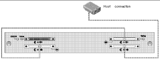
To connect a JBOD in a single-bus configuration to a single host, connect the following ports:

|
Caution - Before you disconnect a cable from the array, the host bus on that cable must be inactive. |

|
Caution - If you change SCSI IDs on the array, ensure that your application points to the correct IDs. |

The following table shows the default SCSI IDs for a 12-drive JBOD when you set up single-bus configuration.
To connect a JBOD in a single-bus configuration to two hosts, connect the following ports:

|
Caution - Before you disconnect a cable from the array, the host bus on that cable must be inactive. |

|
Caution - If you change SCSI IDs on the array, ensure that your application points to the correct IDs. |

The following table shows the default SCSI IDs for a 12-drive JBOD when you set up a single-bus configuration. The SCSI IDs are 0-13, with IDs 6 and 7 reserved for host HBA connections.
There are two important features to note with the dual-bus single-initiator JBOD configuration:
Single-initiator mode has only one host connection on a SCSI channel.
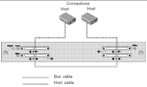
FIGURE B-4 shows a dual-bus JBOD with two host connections using one host connection to each channel (single-initiator mode). In this example, the array can be connected to two hosts or to two ports on one host. For the single host configuration, this is an efficient way to provide mirroring capability for the single host.

Dual-bus, single-initiator mode: SCSI IDs are 8 to 13 on each channel. In the following table, A and B indicate the two host channels. The table shows the IDs assigned to each channel in the dual-bus configuration.
To connect a dual-bus JBOD, perform the following steps.
1. Stop any I/O on the host bus that will have a cable installed on the bus.
2. Connect each JBOD port to a host.

|
Caution - The bottom input ports of the JBOD must have a host connection or external terminator to maintain SCSI bus integrity. |

|
Caution - Before you disconnect a cable from the array, the host bus on that cable must be inactive. |
|
Note - If you change SCSI IDs on the array, ensure that your application points to the correct IDs. |
An enhanced SCSI JBOD I/O module, part number 370-5396-02/50 or higher, is now used in Sun StorEdge 3310 SCSI arrays. The enhanced SCSI JBOD I/O module now supports dual-bus, multi-initiator JBOD configurations.
The new I/O module implements termination power on all ports. Used primarily in Sun Cluster environments, this enhancement provides easier configuration and enables you to use an external terminator, when required, in any of the four SCSI ports.
If you have earlier I/O modules and do not have JBOD I/O modules with part number 370-5396-02/50 or higher, see "Older JBOD Dual-Bus Configurations" in the latest Sun StorEdge 3000 Family FRU Installation Guide. Refer to the same manual for additional single-bus and dual-bus configurations.
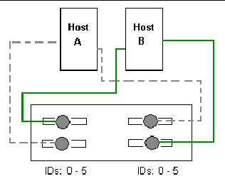
FIGURE B-4 shows a multi-initiator, dual-bus configuration where each host is connected to each host channel. This configuration is common for failover protection in a network cluster environment.
When you remove one or more host cables for maintenance purposes, insert an external terminator into each empty port to maintain the SCSI drive IDs for the active host connections.
|
Note - The I/O module is hot-serviceable, which means that you can replace it or change its cables while the array is powered on, but the SCSI host buses connected to the array must be inactive. |

In this configuration, the dual-bus, multi-initiator mode creates SCSI IDs 0 to 5 on each channel as shown in TABLE B-4.
To connect a dual-bus JBOD to two hosts, perform the following steps.
1. Stop any I/O on the host bus that will have a cable installed on the bus.
2. Connect each JBOD port to a host as shown in FIGURE B-4.
The bottom input ports of the JBOD must have a host connection or external terminator to maintain SCSI bus integrity.
|
Note - Before you disconnect a cable from the array, the host bus on that cable must be inactive. |
For instructions on how to download firmware to disk drives in a JBOD directly attached to a host, refer to the README file in the patch that contains the firmware.
Replacing a disk drive is a straightforward operation that involves first removing the defective disk drive and then installing a replacement drive.
The drive module is hot-swappable; you can replace it while the array is powered on. To replace a disk drive module, first follow the procedure for removing a disk drive and then follow the procedure for installing a new disk drive.
|
Note - If you are removing a disk drive that you do not intend to replace, install an air management sled in its place. See Installing an Air Management Sled for more information. |

To remove a disk drive from an array, perform the following steps.
1. Perform any host software operations necessary to take the disk offline.
2. Unlock the locks with the provided key, and gently pull the plastic front bezel away from the front of the unit so that it drops down and is supported by the two hinged brackets on the sides.
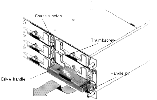
3. Turn the thumbscrew counterclockwise several full turns until the thumbscrew and drive handle are loosened.
4. Gently pull the drive handle upward.
5. Slide the drive module out of the array.
To install a disk drive in an array, perform the following steps.
1. Gently slide the drive module into the drive slot until the handle pins slip into the chassis notch.
2. Lower the disk drive handle until it is vertical.
3. Press and hold the drive handle in while you press the thumbscrew in until it engages the threads.
4. Turn the thumbscrew clockwise until it is finger-tight.
|
Note - To ensure that a thumbscrew is finger-tight, tighten it with a screwdriver and then loosen the thumbscrew counterclockwise a quarter-turn. |
5. Push the plastic front bezel onto the front of the unit until it is seated firmly, and use the key to lock the locks.
6. Perform any operations your host software requires to recognize the new drive and bring it under software control.
The front of an air management sled looks similar to a disk drive module, but the air management sled is an empty box used to maintain optimum airflow in a chassis.
If you have removed a disk drive and do not intend to replace it, insert an air management sled to maintain the optimum airflow inside the chassis. You can install the air management sled by using the same procedure as Installing a New Disk Drive, except that no software operations are necessary.
To enable VERITAS Dynamic Multi-Pathing (DMP) support on VERITAS Volume Manager Version 3.2, ensure the HBA device SCSI initiator IDs are unique and then start the system. Perform the following steps.
1. Create a single-bus, multi-initiator configuration that links two cables to two different HBAs.
For details about creating a single-bus multi-initiator configuration, see Cabling a Single-Bus JBOD with Two Host Connections.
2. Stop the server and at the ok prompt, type:
3. Issue the remaining commands on only one of the paths.
4. Edit or create the nvramrc to set the SCSI-initiator-id to a non-conflicting ID for these devices based on the information returned in step 2.
ok nvedit 0: probe-all install-console banner 1: cd /pci@6,4000/scsi@3 *** your path information here *** 2: 6 " scsi-initiator-id" integer-property 3: device-end 4: banner (Ctrl-c) |
6. Press Ctrl-c, and store the nvramrc by typing:
7. Set the system to use the nvramrc and reset auto-boot by typing:
8. Reset the configuration by typing:
9. Reboot the hosts. A system reboot is required to implement these changes.
Copyright © 2004, Sun Microsystems, Inc. All rights reserved.