| C H A P T E R 2 |
|
Installation |
This chapter describes the system configurations available for the Netra CP2140 board and a brief procedure summary. It also describes how to configure the board and its transition card.
The Netra CP2140 board can be mounted in various enclosures. It can be deployed in various electrical configurations to suit each end-user's requirements. For example, the host board can be used with a transition card and configured to boot from a network as a diskless client. Alternatively, industry-standard PMC and PIM hardware from independent hardware vendors (IHVs) can provide local disk I/O which can optionally be used as a boot path. The basic installation procedure is independent of the type of enclosure used: a floor-mounting rack, a bench-top cabinet, or some other configuration. The memory is user-configurable. See FIGURE 2-1 for Netra CP2140 board hardware configuration examples.
FIGURE 2-1 Examples of Netra CP2140 Board Hardware Configurations
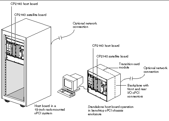
FIGURE 2-1 shows the board hardware configuration options. For more information you see the product website at:
http://www.sun.com/products-n-solutions/nep/hardware/boards/cp2140/
The following items that are related to the Netra CP2140 board can be ordered from Sun Microsystems:
The customer must obtain the other hardware and software as required:
The Netra CP2140 board can accommodate the addition of IHV-built PMC modules to access I/O on their front panels. PMC modules decode their custom I/O from the host's onboard PCI bus B signals.
The XCP2040-TRN I/O Transition Card is installed from the rear of the CompactPCI enclosure and interfaces with the host board's I/O connectors J3, J4, and J5 through the backplane. The backplane carries two RJ45 ports, two serial ports, two parallel ports, one floppy port, two SCSI ports, and two USB ports out to its rear panel. FIGURE 2-2 shows the major components and connectors of the Netra CP2140 board. FIGURE 2-8 shows the physical interface between two Netra CP2140 host boards and two transition cards. To see a typical Netra CP2140 board with memory installed see FIGURE 2-5.
FIGURE 2-2 Netra CP2140 Board Major Components and Connectors
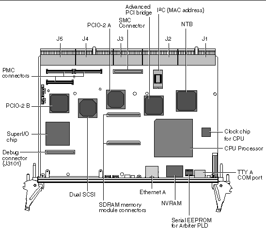
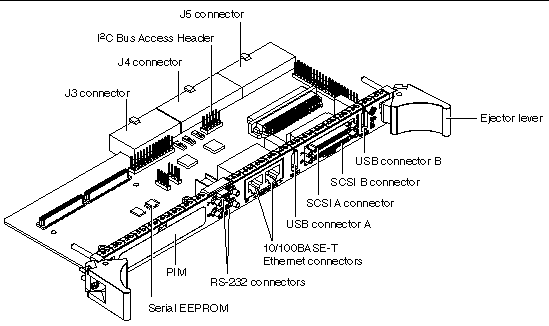
FIGURE 2-3 shows the XCP2040-TRN Transition Card and its connectors.
FIGURE 2-3 XCP2040-TRN Transition Card Connectors
The Netra CP2140 board installs into a customer-supplied 6U chassis. It is important to review the information in the following sections before installing the host board. TABLE 2-2 lists the items to check before installing the board.
|
Verify that all required hardware and software have been received and inventoried. |
|
|
Verify that you have the necessary space to install the host board. Verify that proper space, local area networking (LAN), and environmental preparations have been properly completed. |
Section 2.3.5, Completing Space, Network, and Environmental Planning |
|
Determine the Ethernet and IP address and hostnames and be sure they have been properly allocated and registered at the site. |
Section 2.3.6, Determine Local Network IP Addresses and Host Names |
The Netra CP2140 board system requires various other hardware and software components which are necessary for proper operation. The OEM customer is responsible for providing the following components as required:
 operating environment.
The latest product information along with technical manuals are available on the Web. It is important to read the Netra CP2140 Product Note document (816-4870-xx) that is shipped with the board. For online documents and other information related to the Netra CP2140 board, visit the following Web site:
http://www.sun.com/products-n-solutions/hardware/docs/CPU_boards/
To determine your power supply requirements see Chapter 3.
The Netra CP2140 board requires the latest OpenBoot PROM compatible with your Solaris operating environment. The board is shipped with the version of OpenBoot PROM available at the time of manufacture (version 4.0.x). The OpenBoot PROM might be out-of-date by the time you get this board.
For the latest OpenBoot PROM version, go to the product website:
http://www.sun.com/products-n-solutions/nep/hardware/boards/cp2140
Ensure that the proper physical, electrical, and environmental preparations have been completed before the installation. For a list of the Netra CP2140 board specifications, see Chapter 2. Make sure that the following conditions are met:
You must have the following information to configure the local area network (LAN). Make sure that the IP addresses are not duplicated on different servers (if separated).
Carefully read the Important Safety Information for Sun Hardware Systems (816-7190-xx) document included in your board kit and the following statements before you install or remove any part of the system.
The host board and other boards are extremely sensitive to damage from electrostatic discharge (ESD) caused by the build-up of electrical potential on clothing and other materials.
Follow these safety and ESD preventive measures:
Here are the general steps to configure, install, and set up a Netra CP2140 board system. Ensure that the guidelines outlined in Section 2.3, Preinstallation Checklist are met before configuring and installing the board.
1. Configure the Netra CP2140 board and the associated hardware.
2. Install the CP2140 into an enclosure (see Section 2.10, Installing the Netra CP2140 Board).
3. Install the XCP2040-TRN Transition Card.
4. Connect a SCSI interface, if applicable to your system. Connect the SCSI interface with a cable to one of the SCSI connectors on the XCP2040-TRN Transition Card. Also connect any other necessary cables to the XCP2040-TRN Transition Card. For further details, see Section 2.13, Connecting Devices to a XCP2040-TRN I/O Transition Card.
5. Install the Solaris operating environment (see Section 2.15, Software Installation).
6. Connect the CP2140 to the server using existing Ethernet lines or run the CP2140 as a standalone system (see Section 2.17, Standalone Operation).
7. Set up the system that is using the CP2140.
8. Power on the CP2140 client.
This section provides information on the materials and tools required to perform installation. The minimum tools required to perform installation are:
This section describes how to configure related hardware such as memory modules, PMC modules, and the XCP2040-TRN Transition Card. Most of this hardware must be configured before the CP2140 is installed.
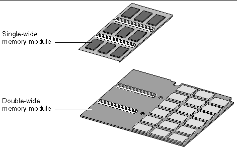
The CP2140 can accommodate both single- and double-wide memory modules. FIGURE 2-4 shows two typical memory modules used on the Netra CP2140 board.
FIGURE 2-4 Single- and Double-wide Memory Modules
Up to two modules in any supported memory configuration can be installed in any combination (512 Mbyte, 1 Gbyte). However, if two memory modules need to be installed and one of the modules is double-wide, the double-wide module should be installed first (on the bottom). Refer to Section 3.1.2, Main Memory for a list of possible memory module configurations.
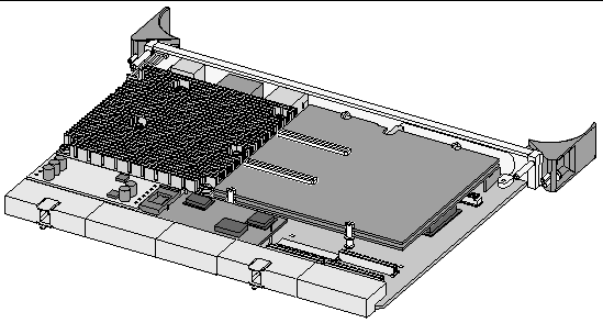
FIGURE 2-5 shows a typical SDRAM memory module installed on a CP2140.
FIGURE 2-5 A Typical Netra CP2140 Board with Memory Modules Installed
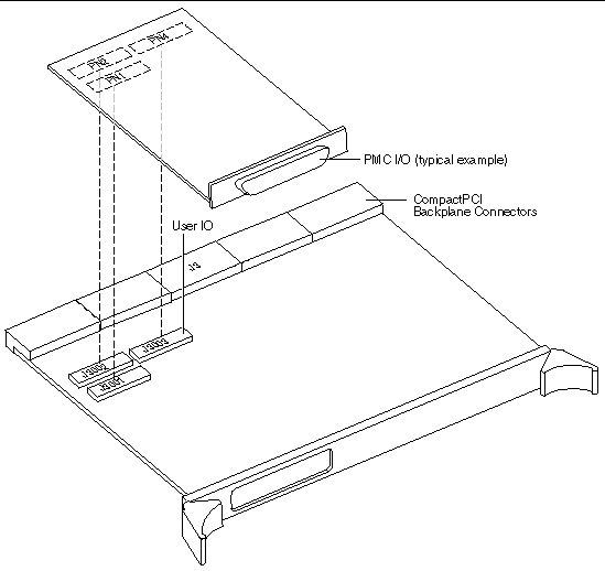
The PCI Mezzanine Card (PMC) is installed on J3001, J3002, and J3003 connectors on the motherboard. These connectors interface with the matching connectors on the PMC board: PN1, PN2, and PN4, respectively. The PMC is secured with two mounting posts and screws. Refer to the user documentation from the PMC card manufacturer on how to install the PMC module. FIGURE 2-6 shows how the PCI Mezzanine Card is installed.
FIGURE 2-6 Installing the PCI Mezzanine Card
This section provides information on installing PIM assemblies and replacing the Serial EEPROM.
Refer to the user documentation from the PIM manufacturer on how to install the PIM module.
This device is installed on the motherboard at the factory. This step is not necessary unless you are installing a replacement board that does not have the host ID. If you must return the CP2140 to the factory, remove this EEPROM from the board before shipping it to the factory. The Serial I2C EEPROM is the MAC address carrier and it stores the backup copy of the board MAC address and host ID information (see Section 5.1.3.4, Serial I2C EEPROM).
FIGURE 2-7 Replacing the Serial I2C EEPROM
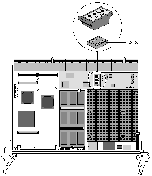
The CP2140 supports the Serial I2C EEPROM. If you must replace the CP2140, remove the Serial I2C EEPROM from the original board and install it on the new CP2140.
To correctly position the EEPROM and to precisely install it on the CP2140, see FIGURE 2-7.
Refer to the installation procedure detailed in the XCP2040-TRN I/O Transition Card Manual for Netra CP2040/CP2140 CompactPCI Board (806-6743-xx) for installing the XCP2040-TRN Transition Card.
Follow all the safety rules described in Section 2.4, Safety when installing any hardware into the CompactPCI chassis enclosure.
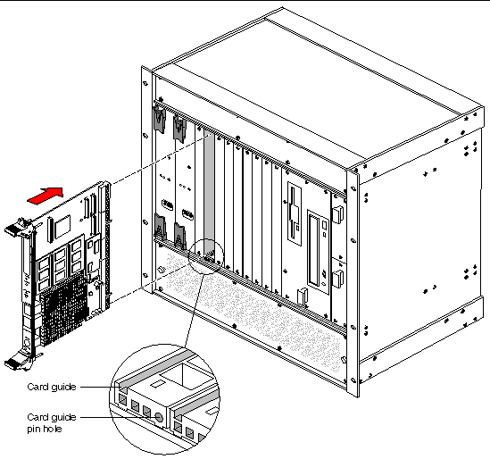
A number of CompactPCI chassis enclosures come with an internal power supply and fan. FIGURE 2-8 shows two Netra CP2140 boards (system host and satellite host) being installed in a CompactPCI chassis.
Smaller CompactPCI enclosures have four board slots. One of these slots is reserved for one 6U form factor board, while the remaining three slots are for either 3U or 6U boards. The larger eight-slot enclosures have two 6U and six 3U slots. In addition, some special CompactPCI enclosures are equipped with a backplane that enables board connection to the front and rear of the chassis.
A CompactPCI chassis contains:
|
Note - The CP2140 can be installed in either a peripheral slot or in a system slot. |
1. Ensure that power is disconnected from the chassis.
The CP2140 can be installed while the chassis is powered-on--however, this method is recommended only when absolutely necessary.
2. Check that the corresponding XCP2040-TRN I/O Transition Card is installed.
Install the transition card before installing the Netra CP2140 board. This step is important if the chassis is powered-on during the installation. The transition card is not hot-swappable. Take the step as a safety precaution.
3. Slide the CP2140 into the appropriate slot on the corresponding top and bottom mounting rails and towards the backplane while gently keeping the board handles pushed inward (see FIGURE 2-8 and FIGURE 2-9).
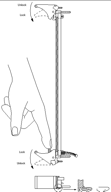
While pushing the board, ensure that the CP2140 extraction levers are aligned perpendicular to the card flange in the unlocked position and that the board connectors are aligned with the transition card connectors.
4. Install two screws at the top and bottom of the front connector plate to secure the board.
FIGURE 2-8 Netra CP2140 Board System Interface: One System Controller Board, One Satellite Board, Two Transition Cards
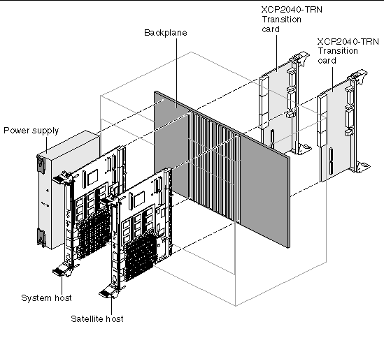
FIGURE 2-9 Netra CP2140 Board Installation (Close-up View)
The transition card can also be fitted with IHV-supplied PCI interface modules (PIMs) which are configured to bring I/O channels to the unit rear panel. A unit of PIM hardware is a kit that includes a card for the PMC slot and a card for the PIM slot on the transition card. A PIM is essentially a rear-panel extension added to a PMC module.
|
Note - If the PMC card (used with the PIM) has front I/O connectors, when you configure PIM rear connector I/O, the front I/O connectors will not be functional. |
You can order the XCP2040-TRN Transition Card, build a compatible custom card, or buy from an IHV. A minimal set of I/O must provide for a boot path for the host board and a path for console I/O to deliver commands and to read board and system status.
This section describes how to connect cables to a computer that contains the CP2140.
1. Connect the Ethernet (if required) where shown in FIGURE 2-3.
2. Use the tip utility on the host system to establish a full-duplex terminal connection with the system containing a CP2140.
3. At the UNIX® prompt in a command tool or shell tool, type:
tip -9600 /dev/ttya
4. Connect a serial cable to Port A (COM port) on the CP2140 or TTYA port of the XCP2040-TRN I/O Transition Card of the target system and to the serial port of the host system.
|
Note - Use shielded cables that are grounded at both ends for serial and USB ports. |
5. Connect any other peripheral devices (such as a printer) to the appropriate connector.
6. Power on the system that contains the CP2140 to run the power-on self-tests (POST).
7. Plug devices into the XCP2040-TRN I/O Transition Card, as necessary.
See XCP2040-TRN I/O Transition Card Manual for Netra CP2040/CP2140 CompactPCI Board (806-6743-xx) for instructions.
If you have connected SCSI peripherals that receive power from a source separate than the system's power supply to a system containing a Netra CP2140 board, you must power on the system prior to powering on SCSI peripherals. After powering on the system, you can safely power on the external SCSI peripherals.
|
Note - If the CP2140 is being used as system host and not functioning as an I/O card, it cannot be hot-swapped. |
A blue LED is lit on a hot-swappable board during extraction process to indicate that it is permissible to extract the board. The blue LED indicates that the system software has been placed in a state for an orderly removal of a board.
During the insertion process, when a board is hot inserted, the blue removal LED is lit again automatically by the system hardware until the hardware connection process is complete. The blue LED is turned off by the software until it indicates once again that the removal of a board is permitted.
Two ejector handles are used for inserting and removing a CompactPCI board. The lower ejector handle is tied to a latch, which when pressed, informs the system that the board is ready for extraction. When the system has unconfigured the board, a blue LED is lit indicating that the board is ready for extraction. You must wait until the blue LED is lit before removing the board.
The basic hot swap is initiated by the cfgadm configure/unconfigure administration command:
The cfgadm command provides configuration administration operations on dynamically reconfigurable hardware resources. Configuration administration is performed at attachment points, places where system software supports dynamic reconfiguration of hardware resources during continued operation of the Solaris operating environment.
Configuration administration distinguishes between hardware resources that are physically present in the server and hardware resources that are configured and visible to the Solaris software. The nature of configuration administration functions are hardware-specific and are performed by calling hardware-specific libraries. Refer to the man pages (by typing man cfgadm) for additional information on the options associated with this command.
1. Type the unconfiguration command:
# cfgadm -c unconfigure pci1:hsc0_slot5
To inform the system to enable the extraction and insertion of a device, if permissible. The blue LED is lit if the process is successful, indicating that the board can be extracted.
2. Remove the I/O board and set it aside.
3. Slide the new I/O board into the top and bottom mounting rails in the same slot into the backplane while gently keeping the board handles in the open position. Once the board is all the way in, lock the ejector handles (see FIGURE 2-10).
The blue LED is lit once the board makes complete contact with the backplane. The LED goes off shortly after the ejector handles are closed, if the hardware initialization of the board is successful. Otherwise, it remains lit, indicating that the board must be replaced.
4. Once the blue LED of the board is off, secure the board to the chassis.
5. Type the configuration command:
# cfgadm -c configure pci1:hsc0_<slot5>
The part of the command in parenthesis indicates the slot in which the board resides.
6. Take any other step necessary for board-specific configuration.
Hot-swapping a line card does not require the system power to be turned off. Refer to the chassis manufacturer's documentation for slot assignments and additional information. In addition, a full hot-swap board does not require running the cfgadm administrative command. The system automatically configures the card for using the system resources. The board-specific configuration steps are still necessary after the completion of host-specific configuration.
Follow these steps to hot-swap a line card in a chassis that contains the Netra CP2140 system host board.
1. Remove the I/O board screws.
2. Release the latches of the I/O board and wait for the blue LED to light.
3. Remove the I/O board and set it aside.
4. Slide the new I/O board into the top and bottom mounting rails in the same slot into the backplane while gently keeping the board handles in the open position. Once the board is all the way in, lock the ejector handles (see FIGURE 2-10).
FIGURE 2-10 shows how to release and to lock the CP2140 injector/ejector handles.
The blue LED is lit once the board makes a complete contact with the backplane. The LED goes off shortly after the ejector handles are closed, if the hardware initialization of the board is successful. Otherwise, it remains lit, indicating that the board must be replaced.
5. Once the blue LED of the board is off, install two screws at the top and bottom of the front connector plate to secure the board.
FIGURE 2-10 Releasing and Locking the Netra CP2140 Board Injector/Ejector Handles
The XCP2040-TRN I/O Transition Card is an interface card that provides access to the following connector features which are supported by the CP2140:
Install the XCP2040-TRN I/O Transition Card as directed in the transition card manual.
1. Connect a single-ended SCSI drive and cable to the internal SCSI connector on the XCP2040-TRN I/O Transition Card.
The internal SCSI connector is more suitable for attaching internal devices to the system.
2. Connect other supported peripheral devices as required.
|
Note - For a detailed description of the XCP2040-TRN I/O Transition Card, refer to XCP2040-TRN I/O Transition Card Manual for Netra CP2040/CP2140 CompactPCI Board (806-6743-xx). |
The CP2140 configuration supports IHV CompactPCI cards. To add CompactPCI cards and drivers, refer to the documentation provided with the CompactPCI card. Usually software drivers and related documentation are provided on the CD or floppy diskettes. Read all documentation furnished with the package. The manufacturer's Web site might also have the latest product and driver information.
1. Halt the operating environment and power down the system.
2. Install the CompactPCI card.
3. Make necessary connections.
5. Boot with -r option (or with -rv for verbose messages).
6. At system prompt, become superuser.
7. Add package using pkgadd command.
|
Note - In a properly configured system, a card can be hot inserted and then manually configured by unsing cfgadm. |
1. Use the prtconf -D command to display the device tree.
It should show the PCI bus instances #0 and #1 for the two PCI buses on the CP2140. There are instances of various PCI cards connected to each one. A PCI card might show up as pciVVVV,DDDD, where VVVV is the vendor ID, for example, 1011 and DDDD is the device ID, for example 008e. If the driver for the card is already loaded, then you might see the device name supplied by the driver in the device tree.
2. Use the modinfo command to see whether the driver for the card is loaded.
Typically the description of the driver contains the name of the product or the vendor.
3. At the OpenBoot PROM prompt, the PCI board is visible in the device tree even if the driver is not installed.
1. Run the following commands and record the output.
prtconf modinfo dmesg cat /etc/driver_aliasescat /etc/path_to_inst
2. Contact the PCI card vendor.
To successfully run a Netra CP2140 board system, consider the following points related to the CompactPCI backplane and cardcage:
This section describes the power-on procedure for the CP2140. This procedure is intended only for advanced UNIX users and system administrators.
a. Position the power supply switch to ON.
b. Use the tip utility to establish a full-duplex terminal connection between the Sun workstation and the CP2140.
c. At the UNIX prompt in a command or shell tool window type:
tip -9600 /dev/ttya
2. Perform the following diagnostic steps.
a. Verify the accuracy of the following information before continuing to the next step.
Make sure all devices are recognized by the system. Ensure that the hard disk drive is recognized as target 0 and that the CD-ROM drive is recognized as
target 6.
For details on output information, see Section 6.6, Determining Firmware Version.
The CP2140 requires the Solaris 8 2/02 operating environment software. CP2000 Supplemental CD 4.0 for Solaris 8 is available that offers additional features for the CP2140 such as CompactPCI net driver support and satellite hot-swap support. CP2000 Supplemental CD 3.1 for Solaris 8 can also be used with the Netra CP2140 board, but does not contain all of the features available on CD 4.0.
For further information on how to obtain the CD, contact your Field Application Engineer.
1. To install the system from the CD , at the ok prompt, enter:
ok boot cdrom
The system boots from the CD and the Solaris operating environment installation begins. Provide appropriate answers to various prompts that are displayed as the system is installed.
2. To install the system from a server, obtain the boot client Ethernet address (the system being built).
a. At the ok prompt (on the system being built), type:
The Ethernet address displayed in the following format: X:X:XX:XX:XX:XX for example: 8:0:20:7e:f6:dc
b. Type the Ethernet address obtained in Step a into the install server as a boot client.
Refer to the Solaris software documentation to set up an install server.
c. At the ok prompt on the client (of the system being built), type:
The system boots from the network and the Solaris software is installed from the network. Various prompts are displayed as the system is installed; answer them as appropriate.
3. After the Solaris operating environment is installed, at the ok prompt, enter:
The system configures itself after the installation.
If the installation is successful, the system boots to a Solaris login prompt.
The minimal necessary infrastructure to enable network computing involves a boot server with networking software and the CP2140. The boot server senses the CP2140 booting up on the network and supplies the client with its boot image: Solaris software.
|
Note - The Netra CP2140 board also depends on a domain network server (DNS) and a network information server (NIS); do not attempt to set up clients on a network without them. |
An administrator can also choose a separate Internet Message Access Protocol version 4 (IMAP4) server and a home directory server. These software services can be installed on a single server or spread out over several servers.
Follow these guidelines to help ensure a successful CP2140 client/server configuration.
The CP2140 provides a complete I/O subsystem and can operate as a standalone computer for development purposes or other special applications. The CP2140 provides two UltraWide single-ended SCSI connections that are accessible through the rear of a special CompactPCI chassis that contains a backplane. This enables connection to a hard drive, tape, or a number of other SCSI devices. Software can be downloaded through the internet or from a CD into a hard drive connected to the XCP2040-TRN I/O Transition Card.
Copyright © 2002, Sun Microsystems, Inc. All rights reserved.