| C H A P T E R 1 |
|
Introduction |
The Netra CP2140 CompactPCI board incorporates a 650-MHz UltraSPARC IIi processor and uses the Solaris 8 operating environment in order to meet enhanced availability requirements. This board also supports advanced architectural capabilities for next-generation network infrastructure requirements.
The Netra CP2140 board is a crucial building block in developing carrier-grade systems. It can function either as a system controller or as a satellite board. As a modular solution, the Netra CP2140 board is easy to configure and install. It is designed to support next-generation requirements, in conjunction with the Netra CP2060/CP2080 satellite CompactPCI boards, for continuous uptime in the core network and access network infrastructures.
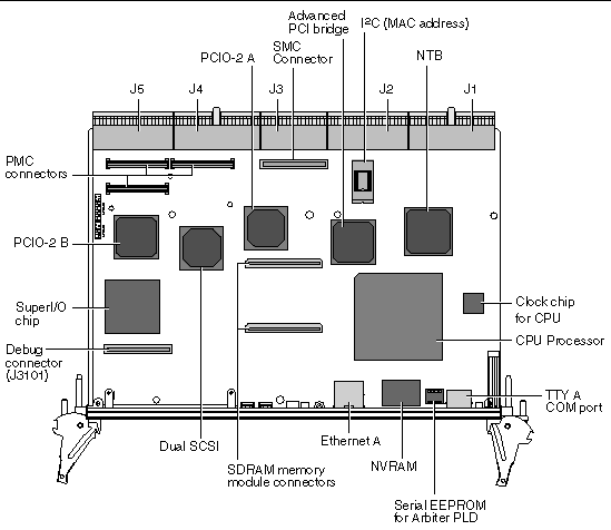
The Netra CP2140 board complies with the PICMG CompactPCI 3.0 specification. In the system host role, the Netra CP2140 board supports Basic, Full, and High- Availability hot swap. FIGURE 1-1 shows the Netra CP2140 board.
FIGURE 1-1 Netra CP2140 Board (Without Heat Sink)

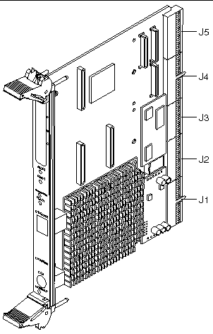
FIGURE 1-2 Typical Netra CP2140 Board System Host or Satellite Host Board


|
Caution - The CPU module, heat sink, System Management Controller, and power module are all integral to the Netra CP2140 board. Any attempt to disassemble or replace these devices on the board voids the warranty (see FIGURE 4-1 for location of devices). |
Systems that conform to CompactPCI specifications require differentiation of chassis board slots depending upon the mode in which a board is to function.
To function as a System Host, a CP2140 processor includes connections to distribute PCI clocks and to receive interrupts from peripherals. It must also be situated in a System Host slot in the CompactPCI segment because only these chassis slots have backplane wiring with the full set of connections required to enable the System Host function. The CP2140 directly controls the CompactPCI peripheral hardware. Netra CP2140 boards assume a System Host role when installed in a PICMG system slot. A system slot is marked with an open triangle legend specified in CompactPCI Specification, PICMG 2.0 R3.0.
The CP2140 can be installed in one of the remaining (non-System Host) slots if the user wants to use it as a Satellite Host.
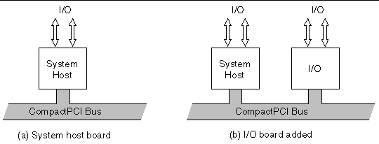
The simplest configurations of the Netra CP2140 board are shown in FIGURE 1-3. They contain one System Host that can supply any input/output (I/O) required by itself (a), or use an added I/O board (b). There is no redundancy in either of these arrangements.
FIGURE 1-3 Non-redundant Netra CP2140 Board HA Configuration - One System Host Board

Satellite Hosts do not control any peripheral I/O outside their own board and are typically used to perform independent processor-intensive tasks.
The CP2140 is designed to support hot-swap operation, system management, and environmental monitoring. These functions are implemented in the System Management Controller which is designed as a mezzanine module on the CP2140. In addition, the CP2140 has PCI mezzanine connectors that enable the connection of a compatible PMC peripheral. The CP2140 supports two 10/100Mbps Ethernet ports and two serial ports, two universal serial bus (USB) ports, two SCSI ports, floppy port, and PS/2 keyboard and mouse port.
TABLE 1-1 summarizes the key features of the CP2140.
|
UltraSPARC IIi 650 MHz processor with internal 512KB integrated cache |
|
|
No on-board memory. Up to 2GB memory is supported via the following memory modules: |
|
|
At approximately 20W ( with 512MB) and 32W (with 2GB) at 650MHz (excluding PMC power). These figures are application dependant. |
|
|
Meets PICMG CompactPCI 3.0 and PCI revision 2.1 specifications |
|
|
The on-board SMC supports the following IPMI commands as specified in the IPMI Specification v1.1.0 Rev 1.1: |
|
|
Solaris 8 2/02 or subsequent compatible version with CP2000 Supplemental CD 4.0 for Solaris 8 (CP2000 Supplemental CD 3.1 for Solaris 8 can also be used with the CP2140 board, but it does not contain all of the features of CD 4.0). |
|
|
Dual 10/100Mbit Ethernet with MII interface to the backplane. Ethernet A port is also routed to the front panel with on-board PHY and magnetics (only front or rear access of this Ethernet A port is enabled, no simultaneous accesses to this port are permitted) |
|
|
|
|
Backplane I/O--accessible through rear transition card faceplate |
|
|
|
|
Dual single ended channel Ultra-SCSI that can support up to 40MB/sec data transfer rate. Both SCSI connectors are brought out to the Transition Card. |
|
|
|
|
Compliant with PMC I/O Module Standard, VIT 36-199X, Draft VTA Standards Organization. Can be achieved when using Sun designed transition card for CP2140. |
|
|
Standard 6U CompactPCI form factor. Fits into a single CompactPCI slot with two memory modules installed. |
The Netra CP2140 board is capable of performing basic hot swap, full hot swap and high-availability (HA) hot swap of a Sun-supported CompactPCI I/O card.
FIGURE 1-4 illustrates the indicators and I/O connectors on the CP2140 front panel. The front panel connectors, buttons, and LEDs from top to bottom are as follows:
FIGURE 1-4 Netra CP2140 I/O Front Panel

The CP2140 requires at least the Solaris 8 2/02 operating environment. The CP2000 Supplemental CD 4.0 for Solaris 8 is available that offers additional features on the Netra CP2140 board, such as driver support and satellite hot-swap support. The CP2000 Supplemental CD 3.1 for Solaris 8 can also be used for the CP2140, but does not contain all of the features of CD 4.0.
For further information on how to obtain CP2000 Supplemental CD 4.0 for Solaris 8, please contact your Field Application Engineer.
This section provides details on how to identify the Netra CP2140 board.
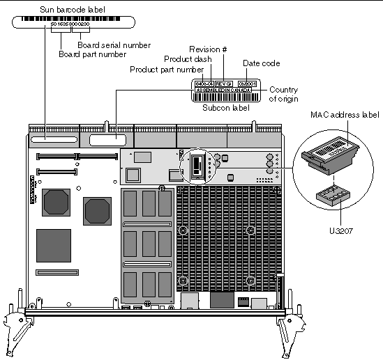
For proper identification of the Netra CP2140 board, labels are provided on the board (see also FIGURE 1-5):
The Sun barcode label provides the following information:
The Subcon label provides the following information:
FIGURE 1-5 Location of Netra CP2140 Board Identification Labels

To display the OpenBoot PROM version, SMC firmware, PLD and SMC FPGA information, type at the OK prompt:
ok .version |
The following is an example of a typical display:
To determine the release number of Solaris operating environment, at the machine-name prompt type:
The Solaris version displays in the following format: X.X.X or X.X
If you have any technical questions or issues that are not addressed in the Netra CP2140 Technical Reference and Installation Manual or on the web site, contact your local sales representative. To contact Sun Enterprise Services in the U.S.,
phone (800) USA-4SUN (800-872-4786). To find the Sun Enterprise Services Worldwide Solution Center nearest you go to this URL:
http://www.sun.com/service/contacting/solution.html
When you call Sun Enterprise Services, be sure to identify the product by the product name: Netra CP2140 board. Also provide its part number (see Determining Netra CP2140 Board Identification Numbers).
The CP2140 comes with a warranty. If your board fails during the warranty period, contact your local Sun Enterprise Services representative for instructions. Before you call, get the Netra CP2140 board date code, part number, and serial number from the labels as described in Determining Netra CP2140 Board Identification Numbers.
Copyright © 2002, Sun Microsystems, Inc. All rights reserved.