| C H A P T E R 3 |
|
Removing and Replacing Hot-Swappable Components |
Hot-swappable components are those that you can install or remove while the system is running, without affecting the rest of the system's capabilities. However, you might have to prepare the operating system prior to the hot-swap operation by performing certain system administration tasks.
In a Netra 440 server, the following components are hot-swappable:
|
Note - Only fan trays 0-2 are hot-swappable; fan tray 3 is a cold-swappable component. Refer to Fan Tray 3 for information on removing and replacing fan tray 3. |
If fan tray 0, 1 or 2 fails, the enclosure status Service Required LED lights and a console message indicates which fan tray failed.

|
Caution - Have a replacement fan tray available before removing a fan tray. A system can only run for approximately 15 minutes with only two fan trays operating before overheating occurs. |

|
Caution - The fan trays contain sharp moving parts. Use extreme caution when servicing the fan trays. |
The part number for fan trays 0-2 is F540-5855.
1. Attach the antistatic wrist strap.
See Avoiding Electrostatic Discharge.
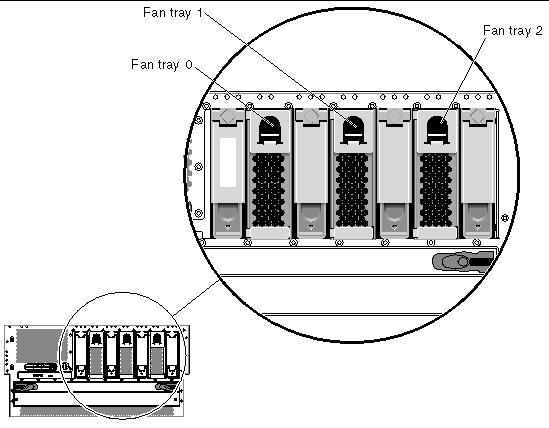
3. Identify the fan tray to be removed and note the bay in which it is installed.
FIGURE 3-1 shows the location of the three fan trays. Refer to the Netra 440 Server Diagnostics and Troubleshooting Guide (817-3886-xx) for more information about isolating failed parts.
4. Pull down on the handle at the top of the fan tray to lower the fan tray catches (FIGURE 3-2).
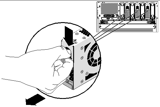
5. Holding the fan tray by the handle, slide the fan tray out of the bay.
|
Note - When you reinstall the fan tray (or a replacement fan tray), ensure that you install the fan tray into the same bay as the one from which it was just removed. |
6. If you are not replacing the fan tray right away, close the system door.

|
Caution - Do not operate the system for longer than 15 minutes without the fan tray in place or the system may overheat. |
2. Align the fan tray to its bay.
Orient the fan tray so that the latch is on the bottom.
|
Note - If you are replacing a fan tray that you removed previously, be sure to install the fan tray into the same bay from which it was removed. |
3. Insert the fan tray into the bay guide rails and slide the fan tray into the bay until it makes firm contact with the backplane.
The system's power supply hot-swap feature enables you to remove a power supply without shutting down the operating system or turning off the system power, provided that at least two other power supplies are online, working, and properly secured.
When removing a power supply using the hot-swap operation, you need to issue a software command to prepare the system for the hot-swap operation. This command also lights up the power supply OK-to-Remove LED. You will use the Advanced Lights Out Manager (ALOM) software tool to initiate a hot-swap operation of the Netra 440 server's power supply. Refer to the Sun Advanced Lights Out Manager User's Guide (817-5481-xx) for additional information, if necessary.
Note that the power supply removal and replacement instructions are identical for both DC- and AC-powered systems.

|
Caution - If a power supply fails, leave the supply in its bay until you are ready to install a replacement. Two power supplies must be present at all times to ensure proper system cooling. |
|
Note - All internal devices, except hard drives, must be installed only by qualified service personnel. |
The following procedure assumes that you are accessing the system console by the default method of connecting to the serial management port (SERIAL MGT) of the Netra 440 server.
The part number for a DC power supply is F300-1567, and the part number for an AC power supply is F300-1674.
If a power supply fails, the enclosure status Service Required LED and that power supply Service Required LED will light.

|
Caution - If a power supply fails and you do not have a replacement available, leave the failed power supply installed to ensure proper system cooling. |

|
Caution - Power supply hot-swap operations should only be conducted by qualified service personnel. |

|
Caution - Attempting to remove a power supply without issuing a software command to isolate it could damage the power supply. |
1. Attach the antistatic wrist strap.
See Avoiding Electrostatic Discharge.
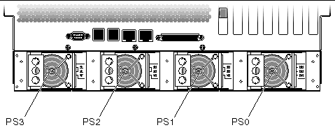
2. At the rear of the system, locate the power supply that you want to remove.
Check the power supply LEDs to determine which power supply is faulty. For more information, see Power Supply LEDs and the Netra 440 Server System Administration Guide (817-3884-xx).
3. To access the ALOM system controller prompt, type the ALOM system controller escape sequence (#.).
4. Type the following ALOM command:
Where power-supply is the name of the power supply to be removed. For example, to remove power supply 1, type the following command:
The OK-to-Remove LED lights on the power supply.

|
Caution - Do not remove a power supply from a running system until the power supply OK-to-Remove LED is lit. |
5. Disconnect the DC or AC power cable from the power supply being removed.
6. Pull the lever on the back of the power supply to the right (FIGURE 3-4).
This disconnects the power supply from the power distribution board inside the server.
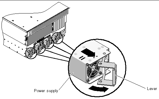
7. Slide the power supply out of the server chassis by pulling on the lever (FIGURE 3-4).

|
Caution - Never insert your hand into the power supply bay while the system is running or while the system is connected to power. Doing so could result in serious personal injury. |
The system console displays a message confirming the removal of the power supply.
The system's power supply hot-swap feature enables you to insert a power supply without shutting down the operating system or turning off the system power.
When installing a power supply, you must insert the power supply and wait for the two green power supply LEDs to light.
The following procedure assumes that you are accessing the system console by the default method of connecting to the serial management port (SERIAL MGT) of the Netra 440 server.

|
Caution - You have limited time to perform a power supply hot-swap operation. You have 10 minutes at sea level and a maximum of 7 minutes at 10,000 feet (3048 meters) to ensure proper system cooling. |
1. Align the new power supply with its bay.
2. Slide the PSU into the server until you feel it engage with the power distribution board inside.
Ensure that the lever does not return to a rightmost position until the power supply engages with the power distribution board. If the lever does return early, the power supply will not engage correctly.
3. Press the lever to the left until it clicks.
Returning the lever to a leftmost position engages the power supply with the power distribution board inside the server.
4. Connect the DC or AC power cable to the power supply.
5. Verify that the power supply is operating correctly.
Check the Service Required, OK-to-Remove, and Power OK LEDs on the power supply. You should hear the power supply fan start spinning and the two green LEDs should light within three seconds after completing a hot-swap installation.
For more information on the power supply LEDs, refer to Power Supply LEDs.
6. Enter the following command to reset the OK-to-Remove LED:
Where N is the power supply number. For example, to turn power on to power supply 0, type:
For information about performing a hot-swap operation on a mirrored hard drive, refer to the Netra 440 Server System Administration Guide (817-3884-xx).
The system's hard drive hot-swap feature enables you to remove a hard drive without shutting down the operating system or turning off the system power. The way in which you remove a hard drive depends on the application you are using and whether you are replacing a drive, adding a new one, or removing a drive permanently.
When you remove a drive using the hot-swap operation, you need to stop the hard drive and take it offline to remove the logical software links to the hard drive, and to reconfigure the file systems so that they now ignore the removed drive. You might also have to reconfigure your application software to operate without the removed drive.
Use the cfgadm command to remove a Netra 440 server's internal hard drive using the hot-swap operation. The following procedure describes the general steps involved, but your specific device names might be different.
The following procedure assumes that you are accessing the system console by the default method of connecting to the serial management port (SERIAL MGT) of the Netra 440 server.

|
Caution - Do not hot-swap drives without the correct preparations. The system supports hot-swapping hard drives, but you must issue a software command before you remove or install a hard drive. |
If a hard drive fails, the enclosure status Service Required LED lights up and a console message indicates which hard drive failed.
If you have not configured the system with two boot drives, you cannot hot-swap a single boot drive. You can only hot-swap the boot drive when you have configured a two-drive mirror of the boot drive for hot-swapping. If the system is configured with a boot drive and data drives, you can hot-swap the data drives, but not the boot drive. For more information on drive mirroring, refer to the Netra 440 Server System Administration Guide (817-3884-xx).
When removing and replacing a hard drive, keep the following points in mind:
The part number for a hard drive is F540-5924, XRA-SC1N2-73G15K.
1. Obtain the logical device name(s) for the device(s) you plan to remove.
Refer to the Netra 440 Server System Administration Guide (817-3884-xx) for more information.
2. Select the drive and stop any activity or applications accessing the hard drive.
3. Unmount any file systems mounted on the hard drive.
4. Attach the antistatic wrist strap.
See Avoiding Electrostatic Discharge.
6. Remove the hard drive from the device tree using the following command:
Where device-name is the name of the hard drive to be removed. For example:
The blue OK-to-Remove hard drive LED lights.
7. Allow the drive to spin down completely.
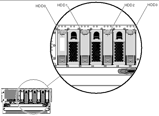
9. Identify the hard drive (HDD) to be removed and note the bay in which it is installed.
FIGURE 3-5 shows the location of the four hard drives. Refer to the Netra 440 Server Diagnostics and Troubleshooting Guide (817-3886-xx) for more information about isolating failed parts.
10. Pinch the hard drive latch up to release the hard drive handle (FIGURE 3-6).
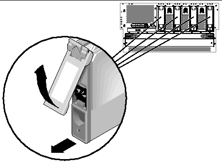
11. Pull the handle away from the hard drive until you feel the hard drive connector disengage from the SCSI backplane connector (FIGURE 3-6).
12. Holding the hard drive by the handle, slide the hard drive out of the hard drive bay.
|
Note - When you reinstall the hard drive (or a replacement drive), be sure to install the hard drive into the same drive bay as the one from which it was just removed. |
13. If you are not replacing the hard drive right away, close the system door.
The system's drive hot-swap feature enables you to insert a hard drive without shutting down the operating system or turning off the system power. When installing a drive, you must insert the hard drive and wait for it to spin up to operating speed. Then you re-create or reconfigure the file systems so that the Solaris OS recognizes the hard drive. Finally, you configure your application (if necessary) to operate with this new drive.
Use the cfgadm command to install a Netra 440 server's internal hard drives using the hot-swap operation. The following procedure describes the general steps involved, but your specific device names might be different.
The following procedure assumes that you are accessing the system console by the default method of connecting to the serial management port (SERIAL MGT) of the Netra 440 server.

|
Caution - Do not hot-swap drives without the correct preparations. The system supports hot-swapping hard drives, but you must issue a software command before you remove or install a hard drive. |
2. Release the hard drive handle on the hard drive.
Pinch the hard drive latch to open the handle.
3. Align the hard drive to its drive bay.
Orient the hard drive so that the hard drive latch is on the bottom.
|
Note - If you are replacing a drive that you removed previously, be sure to install the hard drive into the same drive bay from which it was removed. |
4. Insert the hard drive into the hard drive bay guide rails.
Slide the hard drive into the bay until it barely contacts the backplane.
5. Firmly press the center of the hard drive handle toward the hard drive until the latch closes, securing the hard drive in place.
7. Configure the new hard drive using this command:
where device-name is the name of the hard drive to be configured. For example:
The blue OK-to-Remove LED goes out, and the green Activity LED flashes as the hard drive is added to the device tree.
9. Mount any file systems associated with the hard drive and restart any applications accessing the hard drive.
The air filter is located behind the system door at the front of the system. You should have a replacement air filter available before going through with these procedures. The system may become damaged if you run it without an air filter for an extended period of time. The filters are not designed to be cleaned, so you must completely discard dirty filters and replace them with new clean filters.
The time frame in which the air filter should be replaced varies depending on the environment where the Netra 440 is installed; if the air in the operating environment is especially dirty, you may have to replace the filter more frequently. Reliability may be reduced noticeably when 120 grams of dust has accumulated on the filter, so you should change the filter at that point. In typical locations with high levels of dust and dirt in the air, the recommended service time could be as low as two months. In clean-air environments, the filter may only need to be changed every 18 months or longer.
The following is an example that demonstrates how to calculate service times for the Netra 440 server, assuming that the Netra 440 server has an airflow of approximately 96 cubic feet per minute:
The part number for the air filter pack is X8217A.
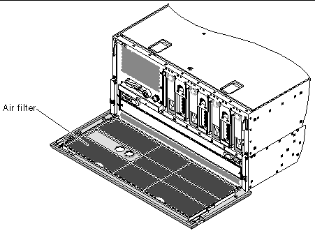
2. Locate the air filter behind the front door panel (FIGURE 3-7).
3. Remove the air filter assembly from the front door panel (FIGURE 3-8).
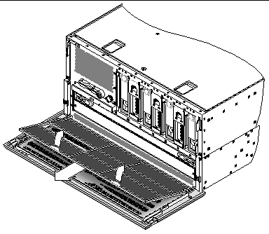
1. Install the air filter assembly into the front door panel (FIGURE 3-8).
Copyright © 2004, Sun Microsystems, Inc. All rights reserved.