| C H A P T E R 4 |
|
Removing and Replacing Cold-Swappable Components |
Cold-swappable components require the system to be powered down before you can remove them.
In a Netra 440 server, the following components are cold-swappable:
The following section describes how to remove and install both the DVD-ROM drive and the DVD-RW drive (both referred to as the DVD drive in this section).
The part numbers for the DVD drives are:
2. Attach the antistatic wrist strap.
See Avoiding Electrostatic Discharge.
4. Press down on the two DVD drive locking tabs, releasing the DVD drive from its cage (FIGURE 4-1).
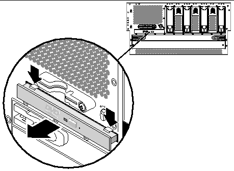
5. Pull out the DVD drive from the front of the system.
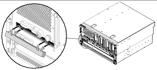
6. If you are not replacing the DVD drive immediately, install the DVD slot cover over the empty DVD space.
Insert the lower two tabs of the DVD cover into the two slots in the empty DVD space, then push the top of the DVD slot cover up until it clicks into place (FIGURE 4-2).
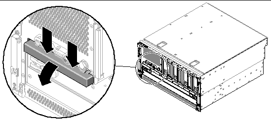
1. Remove the DVD slot cover, if one is installed.
Pull down on the top of the DVD slot cover, then lift it up and away from the empty DVD slot (FIGURE 4-3). Store the DVD slot cover in a safe place.
2. Slide the DVD drive into the system until the two DVD drive locking tabs click into place.
4. Power on the system and perform a configuration reboot.
The system configuration card stores system configuration variables and MAC addresses. For more information on the system configuration card, refer to the Netra 440 Server Product Overview (817-3881-xx).
You can replace a functioning system configuration card and install it into another system. thereby preserving the system's host ID information. Thus, migrating a system configuration card from one system to another can smooth transitions to new or upgraded systems, or quickly bring up a backup system if a primary system becomes unavailable, without disrupting the system's identity on the network. Note that you can only migrate a system configuration card from one Netra 440 server to another Netra 440 server.
If you are replacing a defective system configuration card, you must contact a Sun service representative to obtain a new card with the existing server's host ID and MAC address. Do not reuse an old system configuration card if you have replaced it with a new one with the same host ID and MAC address.
Keep the following points in mind when removing or installing the system configuration card:

|
Caution - Because the system configuration card is crucial for system operation, you must store the SCC safely if you have to remove it from the server, and replace it before restarting the server. |
For a list of OpenBoot configuration variables stored on the system configuration card, refer to the Netra 440 Server System Administration Guide (817-3884-xx).
The part number for the system configuration card is F370-5155.

|
Caution - Attempting to remove the system configuration card while the system is running causes an immediate system shutdown in 60 seconds. |
2. Attach the antistatic wrist strap.
See Avoiding Electrostatic Discharge.
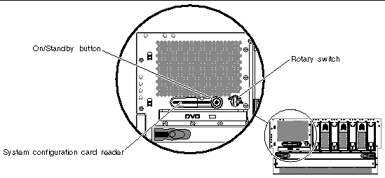
4. Locate the system configuration card reader (FIGURE 4-4).
5. Pull the security post out of its position from in front of the system configuration card (FIGURE 4-5).
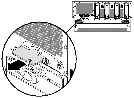
6. Grasp the system configuration card with your fingers and pull it out of the system.
1. Insert the system configuration card into the system configuration card reader, which is at the left of the On/Standby button (FIGURE 4-4).
Orient the system configuration card so that the Sun logo is on the top of the card.
2. Insert the security post into its position in front of the system configuration card.
The system configuration card reader is mounted to the lower piece of the fan tray 3 assembly.
The part number for the system configuration card reader is F540-5856.
2. Attach the antistatic wrist strap.
See Avoiding Electrostatic Discharge.
3. Disconnect the AC or DC power cables from the back of the system.
5. Completely remove the system configuration card from the system configuration card reader.
6. Remove the DVD drive from the front of the system.
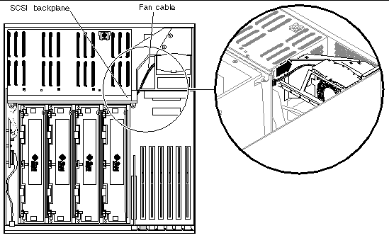
7. Disconnect the fan cable from the SCSI backplane (FIGURE 4-6).
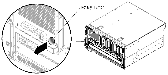
8. Pull the rotary switch away from the system to remove it from the server (FIGURE 4-7).
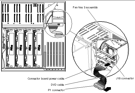
9. Disconnect the connector board power cable from the J18 connector on fan tray 3 (FIGURE 4-8).
Pull the cable out of the connector.
10. Disconnect the P1 DVD cable from the P1 connector on the motherboard (FIGURE 4-8).
Lift up the connector ejector levers as far as they go to release the DVD cable end from the connector, then pull the DVD cable out of the connector.
11. Remove the PCI cards from the system, if necessary.
12. Unscrew the one screw that secures the fan tray 3 assembly to the system (FIGURE 4-9).
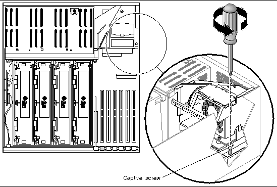
13. Slide the fan tray 3 assembly to the rear of the system to disengage it and lift it up to remove it from the system (FIGURE 4-10).
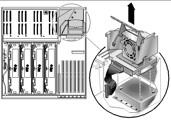
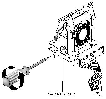
14. Unscrew the one screw to split the fan tray 3 assembly into two pieces (FIGURE 4-11).
The system configuration card reader is mounted to the lower piece of the fan tray 3 assembly, so the entire lower piece of the fan tray 3 assembly will be replaced (FIGURE 4-12). Do not discard the upper piece of the fan tray 3 assembly; you will attach that to the replacement lower piece.
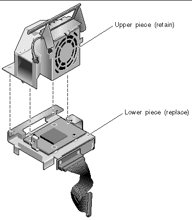
1. Get the replacement lower piece of the fan tray 3 assembly, which contains the system configuration card reader.
2. Assemble the new lower piece of the fan tray 3 assembly with the existing upper piece.
Align the three tabs on the existing upper piece of the fan tray 3 assembly with the three slots in the new lower piece and slide the two pieces completely together.
3. Secure them together using the single captive screw (FIGURE 4-11).
4. Insert the fan tray 3 assembly into the system (FIGURE 4-10).
5. Secure the fan tray 3 assembly to the system using the single captive screw (FIGURE 4-9).
6. Reinstall any long PCI cards, if necessary.
See Installing a PCI Card for those instructions.
7. Connect the connector board power cable at J18 on fan tray 3 (FIGURE 4-8).
8. Connect the DVD cable at P1 on the motherboard (FIGURE 4-8).
9. Install the DVD drive back into the system.
10. Push the rotary switch back into place at the front of the server (FIGURE 4-7).
11. Connect the fan cable to the SCSI backplane (FIGURE 4-6).
13. Connect the AC or DC power cables to the back of the system.
The part number for the SCSI backplane is F540-5853.
2. Attach the antistatic wrist strap.
See Avoiding Electrostatic Discharge.
3. Disconnect the AC or DC power cables from the back of the system.
4. Disengage the hard drives and fan trays 0, 1 and 2 from the SCSI backplane.
a. Pinch the latch up to release the handle.
b. Pull the handle away from the hard drive or fan tray until you feel the connector disengage from the SCSI backplane connector.
You do not have to completely remove the hard drive and fan trays from the bay.
c. Repeat Step a and Step b for each hard drive and fan tray until all the hard drives and fan trays are fully disengaged from the SCSI backplane.
6. Raise the slotted PCI card retainer flap on the fan tray 3 assembly (FIGURE 4-13).
7. Locate the air diverter and SCSI backplane (FIGURE 4-13).
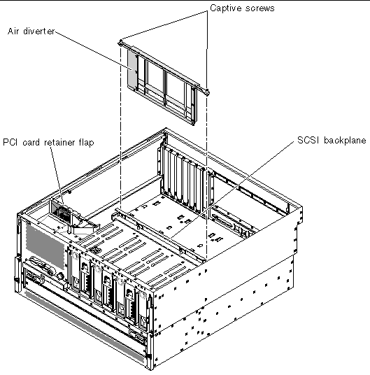
8. Unscrew the two screws from the top of the air diverter and remove the air diverter from the system (FIGURE 4-13).
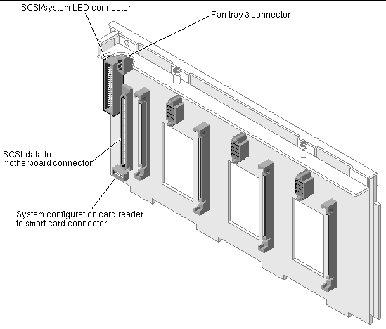
9. Disconnect the cables from the following connectors on the front of the SCSI backplane (the side facing the front of the system):
FIGURE 4-14 shows the locations of these connectors.
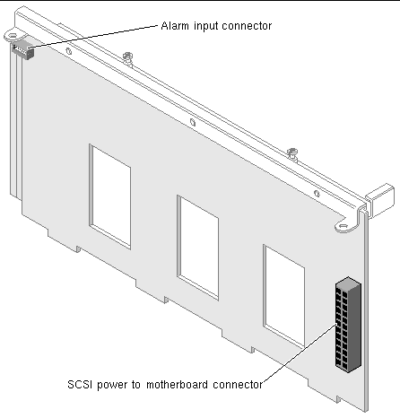
10. Disconnect the cables from the following connectors on the rear of the SCSI backplane (the side facing the rear of the system):
FIGURE 4-15 shows the locations of these connectors.
11. Unscrew the two captive screws that secure the SCSI backplane to the system (FIGURE 4-16).
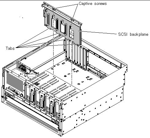
12. Pull the SCSI backplane up and out of the system.
1. Place the SCSI backplane into the system so the four tabs on the bottom of the SCSI backplane align with the slots in the system (FIGURE 4-16).
Ensure that the two captive screws align with their screw holes.
2. Tighten the two captive screws that secure the SCSI backplane to the chassis.
3. Connect the cables to the following connectors on the front of the SCSI backplane (the side facing the front of the system):
FIGURE 4-14 shows the locations of these connectors.
4. Connect the cables to the following connectors on the rear of the SCSI backplane (the side facing the rear of the system):
FIGURE 4-15 shows the locations of these connectors.
5. Insert the air diverter back into the system and tighten the two captive screws to secure it to the top of the SCSI backplane (FIGURE 4-13).
6. Reseat the hard drives and fan trays 0, 1 and 2.
a. Firmly press the center of the handle toward the hard drive or fan tray until the latch closes, securing the hard drive or fan tray in place.
b. Repeat Step a for each hard drive and fan tray until they are all reseated.
8. Connect the AC or DC power cables to the back of the system.

|
Caution - Fan tray 3 contains sharp moving parts. Use extreme caution when servicing this fan tray. |
The part number for fan tray 3 is F540-6069.

|
Caution - Do not attempt to operate the system without fan tray 3 installed. Doing so could overheat and seriously damage the system. |
If fan tray 3 fails, the Service Required LED from the enclosure status indicators lights.
2. Attach the antistatic wrist strap.
See Avoiding Electrostatic Discharge.
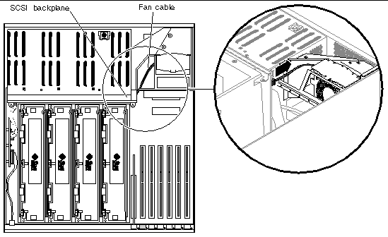
4. Disconnect the fan cable from the SCSI backplane (FIGURE 4-17).
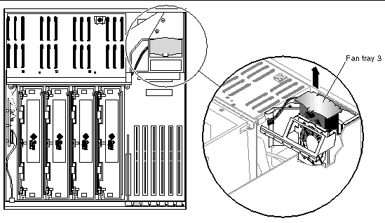
5. Grab the metal plate at the top of fan tray 3 and pull fan tray 3 up and out of the system (FIGURE 4-18).

|
Caution - Do not power on the system without a functioning fan tray 3 installed. Doing so could overheat and seriously damage the system. |
1. Align the tabs on fan tray 3 with their corresponding slots in the chassis (FIGURE 4-18).
The side tab fits into a slot in the chassis side. The two bottom tabs correspond to two slots in the bottom of the chassis.
2. Insert fan tray 3 into the system until it is firmly seated.
3. Connect the fan cable to the SCSI backplane.
The part numbers for the CPU/memory module are:
If a CPU/memory module fails, POST diagnostics alerts ALOM to light the enclosure status Service Required LED.
2. Attach the antistatic wrist strap.
See Avoiding Electrostatic Discharge.
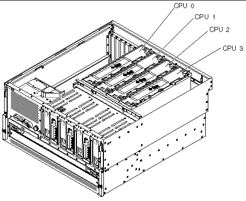
4. Identify the CPU/memory module to be removed (FIGURE 4-19).
Refer to the Netra 440 Server Diagnostics and Troubleshooting Guide (817-3886-xx) for information about isolating failed parts.
5. Loosen the two Phillips No. 2 captive screws securing the CPU/memory module to the CPU cage (FIGURE 4-20).
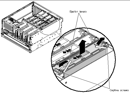
6. Rotate the CPU/memory module ejector levers upward so that the CPU/memory module connectors disengage from the CPU cage (FIGURE 4-20).
7. Pull the CPU/memory module from the chassis by the levers and place it on an antistatic mat.
Support the CPU/memory module from underneath as you transfer it to the antistatic mat.

|
Caution - The CPU/memory module can be hot. Handle the CPU/memory module carefully to avoid injury. |
1. Identify the CPU/memory module slot into which you want to install the CPU/memory module.
The CPU/memory module slots are marked on the bottom of the CPU cage.
2. Inspect the CPU/memory module connector and the motherboard connector for foreign objects.
3. Ensure that the ejector levers on the CPU/memory module are rotated up to a 90-degree angle.
4. Slide the CPU/memory module into the guides in the CPU cage.
Slide the CPU/memory module into the chassis until the connectors on the module begin to engage the socket on the motherboard.
5. Push down on both ejector levers, simultaneously, until the levers are completely pressed into their slots.
|
Note - Do not press down directly on the CPU/memory module. Let the levers press the CPU/memory module into its socket. |
6. Tighten the two Phillips No. 2 captive screws that secure the CPU/memory module to the CPU cage.
7. Repeat Step 1 through Step 6 for every CPU/memory module that you want to install.
If you are installing several CPU/memory modules at one time, once you have installed the final CPU/memory module, you should press down on each of the CPU/memory modules one last time to verify that they are all fully seated.
The Netra 440 server uses 2.5-volt, high-capacity double data-rate dual inline memory modules (DDR DIMMs) with error-correcting code (ECC). The system supports DIMMs with 512-Mbyte and 1-Gbyte capacities.
Within each CPU/memory module, the four DIMM slots are organized into groups of two. The system reads from, or writes to, both DIMMs in a group simultaneously. DIMMs, therefore, must be added in pairs. The figure below shows the DIMM slots and DIMM groups on a Netra 440 server CPU/memory module. Adjacent slots belong to the same DIMM group. The two groups are designated 0 and 1.
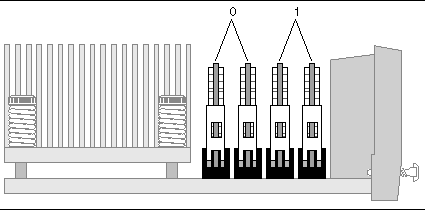
You must physically remove a CPU/memory module from the system before you can install or remove DIMMs. The DIMMs must be added in pairs within the same DIMM group, and each pair used must have two identical DIMMs installed--that is, both DIMMs in each group must be from the same manufacturing vendor and must have the same capacity (for example, two 512-Mbyte DIMMs or two 1-Gbyte DIMMs).
|
Note - Each CPU/memory module must be populated with a minimum of two DIMMs, installed in either group 0 or group 1. |

|
Caution - DIMMs are made of electronic components that are extremely sensitive to static electricity. Static electricity from your clothes or work environment can destroy the DIMM. Do not remove a DIMM from its antistatic packaging until you are ready to install it on the CPU/memory module. Handle the DIMM only by its edges. Do not touch the components or any metal part. Always wear an antistatic grounding strap when you handle the DIMM. For more information, see Avoiding Electrostatic Discharge. |
You can maximize the system's memory bandwidth by taking advantage of its memory interleaving capabilities. The Netra 440 server supports two-way interleaving. In most cases, higher interleaving results in improved system performance. However, actual performance results can vary depending on the system application. Two-way interleaving occurs automatically in any DIMM bank where the DIMM capacities in DIMM group 1 do not match the capacities used in a DIMM group 2. For optimum performance, install identical DIMMs in all four slots in a CPU/memory module.
Keep the following points in mind when removing or installing a memory module:
|
Note - If DIMMs of different densities and speeds are installed as a pair, both DIMMs will operate at the lower density and slower speed. |
The part numbers for the memory modules are:
If a memory module (DIMM) fails, POST diagnostics alerts ALOM to light the enclosure status Service Required LED.

|
Caution - DIMMs are made of electronic components that are extremely sensitive to static electricity. Static electricity from your clothes or work environment can destroy the DIMM. Do not remove a DIMM from its antistatic packaging until you are ready to install it on the CPU/memory module. Handle the DIMM only by its edges. Do not touch the components or any metal part. Always wear an antistatic grounding strap when you handle the DIMM. For more information, see Avoiding Electrostatic Discharge. |

|
Caution - The CPU/memory module and the DIMMs can be hot. Handle the CPU/memory module and the DIMMs carefully to avoid injury. |
2. Attach the antistatic wrist strap.
See Avoiding Electrostatic Discharge.
4. Remove the appropriate CPU/memory module from the system.
See Removing a CPU/Memory Module.
5. Identify the memory module to be removed.
Refer to the Netra 440 Server Diagnostics and Troubleshooting Guide (817-3886-xx) for information about isolating failed parts.
6. Push down on the ejector levers on each side of the memory module, simultaneously, until the memory module ejects from its socket (FIGURE 4-22).
Apply even pressure on both levers.
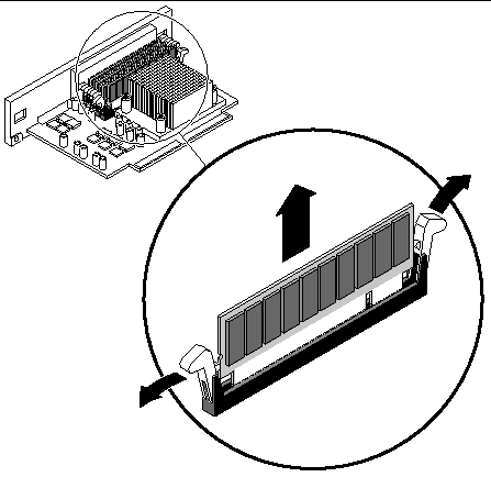
7. Grasp the top corners of the memory module and pull it up and out of its socket.
8. Place the memory module on an antistatic mat.
9. Repeat Step 5 through Step 8 for all the memory modules to be removed.

|
Caution - DIMMs are made of electronic components that are extremely sensitive to static electricity. Static electricity from your clothes or work environment can destroy the DIMM. Do not remove a DIMM from its antistatic packaging until you are ready to install it on the CPU/memory module. Handle the DIMM only by its edges. Do not touch the components or any metal part. Always wear an antistatic grounding strap when you handle the DIMM. For more information, see Avoiding Electrostatic Discharge. |

|
Caution - The CPU/memory module and the DIMMs can be hot. Handle the CPU/memory module and the DIMMs carefully to avoid injury. |
1. Locate the slot into which you are installing the memory module.
2. Rotate out the memory module ejector levers for that slot.
3. Holding the bottom edge of the module parallel to its socket, carefully align the module so that each of its contacts is centered on a socket pin.
Ensure that the memory module is correctly oriented. A notch along the bottom of the memory module corresponds to a tab on the socket.
4. Push firmly and evenly on both ends of the memory module until its bottom edge is firmly seated in the socket.
You hear a click when the ejector levers lock into place.
5. Repeat Step 1 through Step 4 for all memory modules to be installed.
6. Install the CPU/memory module back into the system.
See Installing a CPU/Memory Module.
Keep the following points in mind when removing or installing a PCI card:
|
Note - A 33-MHz PCI card installed in to any of the 66-MHz slots causes that bus to operate at 33 MHz. |
|
Note - All internal devices, except hard drives, must be installed only by qualified service personnel. |
The part number for the PCI card will vary, depending on the card. Contact your local Sun service representative for more information.
2. Attach the antistatic wrist strap.
See Avoiding Electrostatic Discharge.
4. Disconnect any external cables attached to the faceplate of the PCI card.
5. Disconnect any internal cables connected to the PCI card internal connectors.
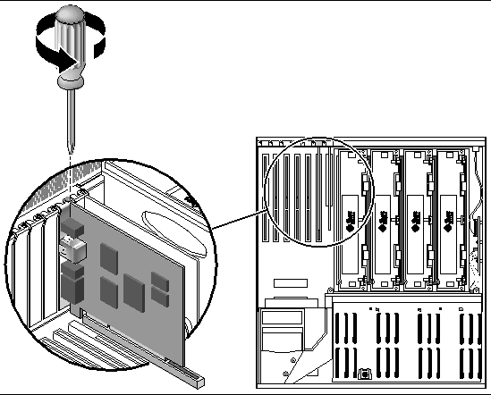
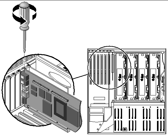
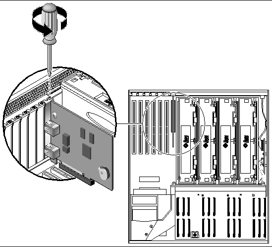
6. Remove the Phillips No. 1 screw securing the card to the system back panel.
FIGURE 4-23 shows the screw being removed for a regular PCI card, and FIGURE 4-24 shows the screw being removed from a long PCI card.
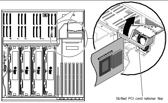
7. If you are removing a long PCI card, raise the slotted PCI card retainer flap on the fan tray 3 assembly (FIGURE 4-25).
8. Pull the PCI card from its slot.
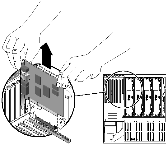
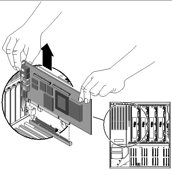
FIGURE 4-26 shows a regular PCI card being removed from the system, and FIGURE 4-27 shows a long PCI card being removed from the system.
Hold the card by the faceplate and its opposite edge. Pull up while rocking the card from end to end until it is freed from its slot.

|
Caution - Do not apply excessive force to one end or one side of the card. Doing so could damage the card. |
9. Place the PCI card on an antistatic mat.
10. If you are not replacing the PCI card, install a PCI filler panel and reassemble the system.
The PCI filler panel prevents debris from entering the system and ensures proper cooling.
a. Slide the filler panel into the appropriate slot.
b. Replace the Phillips No. 1 screw that secures the filler panel to the system back panel.
c. If you removed a long PCI card, lower the slotted PCI card retainer flap on the fan tray 3 assembly (FIGURE 4-25).
1. Power off the system, if you have not done so already.
2. Remove the top cover, if you have not done so already.
|
Note - PCI slots 2, 4, and 5 can handle 33-MHz or 66-MHz cards. PCI slots 0, 1, and 3 are reserved for 33-MHz cards. |
4. If you are installing a PCI card into an unused slot, remove the corresponding filler panel from the system back panel. Otherwise, go to Step 3.
a. Remove the Phillips No. 1 screw securing the PCI filler panel to the system back panel.
b. Lift out the filler panel and save it for future use.
c. If you are installing a long PCI card, raise the slotted PCI card retainer flap on the fan tray 3 assembly (FIGURE 4-25).
5. Insert the PCI card into the appropriate slot on the motherboard.
Ensure that the faceplate of the PCI card is not bent. A bent faceplate could affect the installation of the card.
a. Insert the faceplate end of the card into the appropriate opening in the back panel.
b. Push the card into the corresponding connector on the motherboard.
Apply even pressure along each edge of the card.

|
Caution - Do not apply excessive force to one end or one side of the card. Doing so could damage the card or the motherboard connector. |
6. Secure the PCI card faceplate to the system back panel with the Phillips No. 1 screw.
7. If you are installing a long PCI card, lower the slotted PCI card retainer flap on the fan tray 3 assembly onto the long PCI card.
8. If necessary, connect any internal cables to the PCI card internal connectors.
9. If necessary, connect any external cables to the PCI card.
11. Perform a reconfiguration boot on the system so that the system is able to recognize the new PCI card.
See Initiating a Reconfiguration Boot.
12. Run the OpenBoot diagnostics tests to verify that the system functions correctly with the new PCI card you have just installed.
For additional information, see the Netra 440 Server System Administration Guide (817-3884-xx).
The ALOM serial management port (labeled SERIAL MGT) and network management port (labeled NET MGT) are present in the Solaris OS device tree as /dev/ttya, and in the OpenBoot configuration variables as ttya. However, the serial management port does not function as a standard serial connection. If you want to attach a standard serial device to the system (such as a printer), you need to use the DB-9 connector on the system back panel, which corresponds to /dev/ttyb in the Solaris OS device tree, and as ttyb in the OpenBoot configuration variables. See the Netra 440 Server Product Overview (817-3881-xx) for more information.
|
Note - All internal devices, except hard drives, must be installed only by qualified service personnel. |
The part number for the ALOM system controller card is F501-6346.
2. Attach the antistatic wrist strap.
See Avoiding Electrostatic Discharge.
3. Disconnect the AC or DC power cables from the back of the system.
5. Locate the ALOM system controller card.
6. Disconnect any external cables attached to the faceplate of the ALOM system controller card.
Note and label cable connector locations.
7. Remove the Phillips No. 1 screw securing the card to the system back panel (FIGURE 4-28).

|
Caution - Ensure that the power cords are disconnected from the system before removing the ALOM system controller card. |

|
Caution - Follow the instructions in the next step carefully or you may damage the ALOM system controller card or the motherboard. |
8. Using equal force on both ends of the ALOM system controller card, pull the card straight up from its slot (FIGURE 4-29).
Hold the card by the faceplate and its opposite edge. Pull up while rocking the card from end to end until it is freed from its slot.
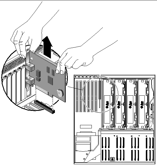
9. Place the ALOM system controller card on an antistatic mat.
1. Locate the slot for the ALOM system controller card.

|
Caution - Follow the instructions in the next step carefully or you may damage the ALOM system controller card or the motherboard. |
2. Insert the ALOM system controller card into its slot on the motherboard (FIGURE 4-30).
a. Insert the faceplate end of the card into the appropriate opening in the system back panel.
b. Using both hands to apply even pressure along the edge of the card, push the card into the connectors on the motherboard.
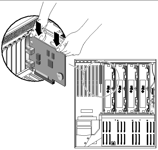
3. Secure the ALOM system controller card faceplate to the back panel with the Phillips No. 1 screw.
4. Connect the cables to the faceplate of the ALOM system controller card.
6. Connect the AC or DC power cables to the back of the system.
The part number for the alarm card is F595-7287.
2. Attach the antistatic wrist strap.
See Avoiding Electrostatic Discharge.
3. Disconnect the AC or DC power cables from the back of the system.
4. Remove the two screws that secure the alarm port connector to the rear of the system (FIGURE 4-31).
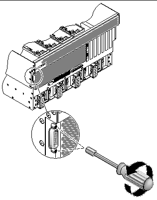
6. Locate the alarm card mounted on the inside of the server (FIGURE 4-32).
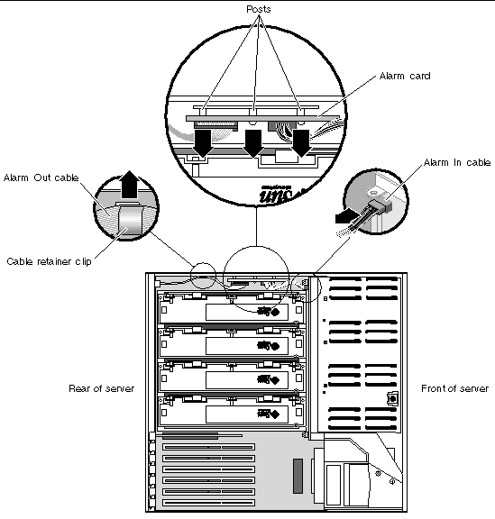
7. Disconnect the Alarm In cable from the SCSI backplane (FIGURE 4-32).
8. Remove the Alarm Out cable from the cable retainer clip on the side of the server (FIGURE 4-32).
9. Press against the sides of the alarm card to first disengage the bottom of the alarm card from the two posts on the side of the server, then the top of the alarm card from the one post on the side of the server (FIGURE 4-32).
10. Remove the alarm card and cables from the system.
1. Insert the alarm card and cables into the system (FIGURE 4-32).
2. Align the three holes in the alarm card with the three posts on the inside of the server and press firmly to secure the alarm card to the system (FIGURE 4-32).
3. Connect the Alarm In cable to the SCSI backplane (FIGURE 4-32).
4. Route the Alarm Out cable through the clip on the inside of the server (FIGURE 4-32).
5. Insert the alarm port connector through the alarm port hole at the rear of the server and secure it using the two screw (FIGURE 4-31)s.
7. Connect the AC or DC power cables to the back of the system.
The part number for the power distribution board is F540-5854.
2. Attach the antistatic wrist strap.
See Avoiding Electrostatic Discharge.
3. Disconnect the AC or DC power cables from all of the power supplies at the back of the system.
4. Disengage all of the power supplies from the power distribution board.
a. Go to the back of the system and pull the lever on the power supply to the right (FIGURE 4-33).
This disconnects the power supply from the power distribution board.
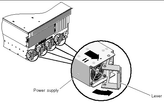
b. Pull the power supply out of its bay just enough to disengage the power supply connectors from the power distribution board connectors.
Leave the power supply in its bay, but disconnected from the power distribution board.
c. Repeat Step a and Step b for the remaining three power supplies.
5. At the front of the system, open the system door.
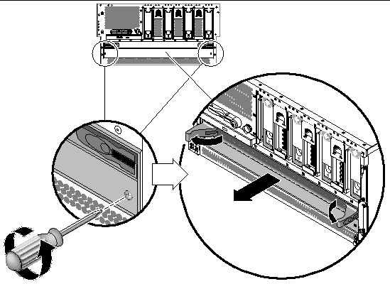
6. Using a Phillips screwdriver, loosen the two captive screws that secure the base of the power distribution board to the server (FIGURE 4-34).
7. Pull on the ejector latches and pull the power distribution board out if its bay (FIGURE 4-34).
1. At the front of the system, slide the power distribution board partly back into the system until you first feel resistance.
Do not push the power distribution board all the way in.
2. Use the ejector levers at the front of the power distribution board to fully seat the module all the way into the system.
3. Using a Phillips screwdriver, tighten the two captive screws to secure the base of the power distribution board to the server.
5. At the rear of the system, fully push all four of the power supplies back into the system.
6. Push the lever on each power supply to the left to fully seat it in the system.
7. Connect the AC or DC power cables to all of the power supplies at the back of the system.
The part number for the motherboard is F540-5919.
2. Attach the antistatic wrist strap.
See Avoiding Electrostatic Discharge.
3. Disconnect the AC or DC power cables from the back of the system.
5. Remove all CPU/memory modules.
See Removing a CPU/Memory Module.
See Removing a PCI Card.
7. Remove the ALOM system controller card.
See Removing the ALOM System Controller Card.
9. Locate the air diverter (FIGURE 4-35).
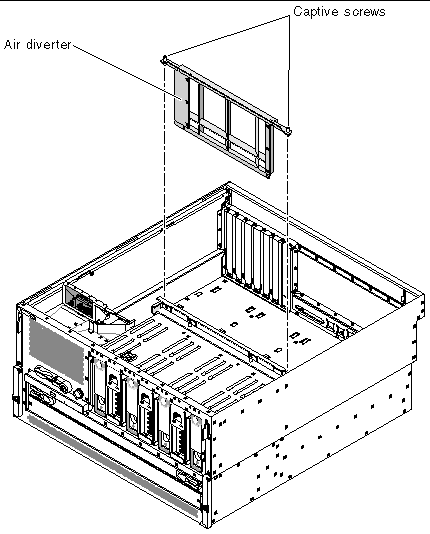
10. Unscrew the two screws from the top of the air diverter and remove the air diverter from the system (FIGURE 4-35).
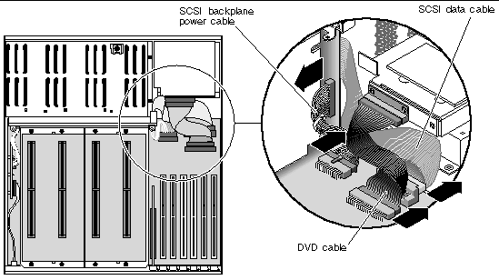
11. Disconnect the P5 SCSI backplane power cable from both ends (the end at P5 on the motherboard and the end on the SCSI backplane). See FIGURE 4-36.
Press the locking tab on the P5 motherboard end and pull it out of the connector. Hold the SCSI backplane end by the edges and gently rock the cable from side to side as you pull it out of the connector.
12. Disconnect the P1 DVD cable end at P1 on the motherboard (FIGURE 4-36).
Lift up the connector ejector levers as far as they go to release the DVD cable end from the connector, then pull the DVD cable out of the connector.
13. Disconnect the P3 SCSI data cable end at P3 on the motherboard (FIGURE 4-36).
Hold the cable end by the edges and gently rock the cable from side to side as you pull it out of the connector.
14. Disengage the power supplies from the power distribution board.
a. Go to the back of the system and pull the lever on the back of a power supply to the right (FIGURE 4-37).
This disconnects the power supply from the power distribution board inside the server.
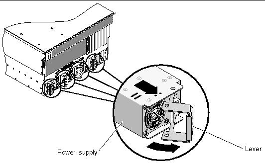
b. Pull the power supply out of its bay just enough to disengage the power supply connectors from the power distribution board connectors.
Leave the power supply in its bay, but disconnected from the power distribution board.
c. Repeat Step a and Step b for the remaining three power supplies.
15. Disengage the power distribution board from the motherboard.
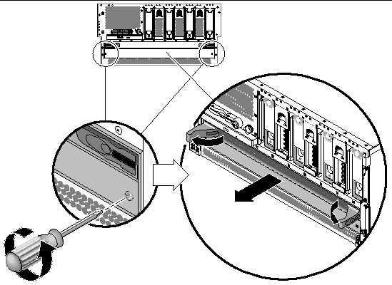
a. Using a Phillips screwdriver, loosen the two captive screws that secure the base of the power distribution board to the server (FIGURE 4-38).
b. Pull on the ejector latches to unseat the power distribution board from the motherboard (FIGURE 4-38).
Leave the power distribution board in its bay, but disconnected from the motherboard.
16. At the back of the system, disconnect any external cables attached to the motherboard.
Note and label connector locations.
17. Unscrew the three Phillips No. 2 screws that secure the motherboard to back of the system (FIGURE 4-39).
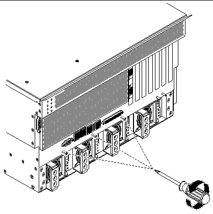
18. Slide the motherboard slightly toward the front of the system to disengage the tabs at the bottom of the motherboard from the slots in the system.
19. Pull the motherboard up and out to remove it from the system (FIGURE 4-40).
Remove the motherboard at an angle to clear the sides of the system. You may have to rock the motherboard from side-to-side to remove it cleanly.
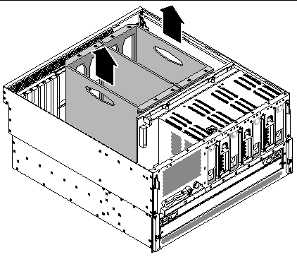
1. Align the motherboard with the chassis so the CPU cage sits directly behind the hard drives and fan trays (FIGURE 4-40).
2. Lower the motherboard into the chassis at an angle, inserting the CPU side of the board first.
Ensure that the DVD cable and the SCSI cable are folded back out of the way. You might have to rock the motherboard from side-to-side to install it cleanly.
3. With the motherboard sitting flat on the base of the system, slide the motherboard toward the back of the system to engage the tabs at the bottom of the motherboard with the slots at the base of the system.
4. Tighten the three Phillips No. 2 screws to secure the motherboard to the system (FIGURE 4-39).
5. Connect the P3 SCSI data cable end at P3 on the motherboard.
6. Connect the P1 DVD-ROM cable end at P1 on the motherboard.
a. Ensure that the ejector levers are rotated up before inserting the cable.
b. Push the cable end into its connector until the ejector levers lie flat.
7. Connect the P5 SCSI backplane power cable end at P5 on the motherboard.
8. At the front of the system, slide the power distribution board back into the system until it is engaged with the motherboard.
Use the ejector levers at the front of the power distribution board to fully secure it against the motherboard.
9. Tighten the two captive screws to completely secure the power distribution board to the motherboard.
10. At the rear of the system, fully push all four of the power supplies back into the system.
11. Push the lever on each power supply to the right to fully seat it in the system.
12. Reinsert the air diverter into the system and tighten the two screws at the top of the air diverter to secure it to the system.
See Installing the Alarm Card.
14. Install the ALOM system controller card.
See Installing the ALOM System Controller Card.
16. Install all CPU/memory modules.
See Installing a CPU/Memory Module.
18. Connect the AC or DC power cables to the back of the system.
Copyright © 2004, Sun Microsystems, Inc. All rights reserved.