| C H A P T E R 4 |
|
Firmware |
The Netra CP2300 board contains a modular firmware architecture that gives you latitude in controlling boot initialization. You can customize the initialization, test the firmware, and even enable the installation of a custom operating system.
This platform also employs the System Management Controller (SMC)--described in Section 5.6, System Management Controller--which controls the system management and hot-swap control, and some board hardware. The SMC configuration is controlled by separate firmware.
This chapter contains the following sections:
Control flow at board startup is shown in FIGURE 4-1. Execution begins in Firmware Common Operations and Reset Environment (CORE)--which includes Basic POST (BPOST). It passes to Comprehensive POST (CPOST) and Extended POST (EPOST), if these are present, before returning to firmware CORE and on to OpenBoot PROM. The test execution path is determined by environment variables.
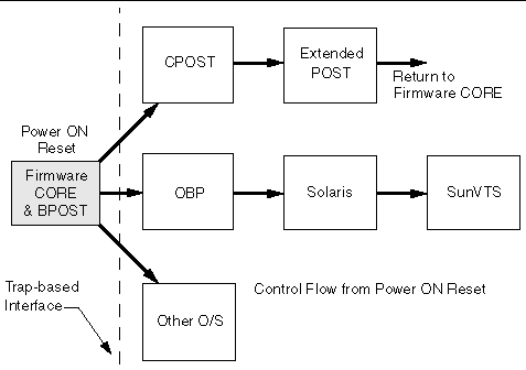
Firmware CORE provides the following functionality:
 processors are designed with a common software trap structure that is useful for this common programming interface, so that clients may not need to carry another copy of those drivers and may use those services provided by firmware CORE until their driver takes over.
BPOST is integrated into firmware CORE. BPOST tests are interleaved with the initialization activities of firmware CORE to present a foundation of validated and initialized hardware to run subsequent code such as that in CPOST or OpenBoot PROM. The tests listed in TABLE 4-1 are examples of CORE and BPOST flow of execution.
|
Note - Not all of the hardware listed in this table is present on this platform. When a hardware item is not detected by the firmware, this firmware makes no attempt to test or initialize it. |
Because BPOST runs from PROM, its extent of testing is limited to that needed by modules that are loaded later. Such a module, for example CPOST, can perform comprehensive testing more quickly because it executes from DRAM.
|
Initializes XBus and UPA/PCI and PCI/PCI bridges in path between CPU and XBus devices. |
|
|
Perform basic diagnostics on caches & MMUs[1]. |
|
|
Perform partial memory test[2]. |
|
|
Setup I/D MMUs with valid mappings; enable MMUs and I/D caches. |
|
|
Copy firmware CORE into memory and transfer control to the RAM copy. |
|
|
Execute POST dropin| |
|
|
Locate the client in PROM. If found, copy into memory and transfer control to it. |
|
CPOST contains tests for higher-level board functions. By placing these tests in a separate module, the user has the option of performing them and the developer can substitute them with other tests. Examples of CPOST tests are:
EPOST is used for additional POST code dropins that are provided by the user.
Rather than executing the initialization code that formerly existed in OpenBoot PROM for prior Sun board platforms, OpenBoot PROM now makes calls to the traps laid down by firmware CORE. OpenBoot PROM exists in the form of a dropin in the system flash memory area.
OpenBoot PROM probes for devices and builds the device tree, which is a table that contains entries for how drivers communicate with connected hardware. Each line, or entry, of the device tree is a reference for the node entry for the peripheral in the /dev directory. The device tree is inherited by Solaris software as it is booted. An example of a device tree is shown below. The device tree can be seen by directory in the / directory. The device tree can be seen by typing show-devs at the ok prompt. An example of a device tree appears below.
The OpenBoot PROM also contains aliases for some of the devices shown in the device tree. These aliases can simplify hardware access at the ok prompt. CODE EXAMPLE 4-2 shows how the OpenBoot devalias command lists the available device tree aliases.
This section provides some information on the CORE SRAM variables and the configuration variables. Firmware configuration variables are saved in the 8 Kbyte I2C serial EEPROM. The EEPROM's contents are preserved across board power-cycles.
The key combinations listed in TABLE 4-2 can be used to control the flow of execution at system boot. These key combinations must be pressed when you turn the power on.
The Netra CP2300 boards support USB keyboards.
TABLE 4-3 describes the OpenBoot PROM configuration variables stored in the NVRAM and displayed by the OpenBoot PROM printenv command. Use the setenv OpenBoot command to modify the environment variables. The boot process is controlled by several variables (see TABLE 4-4). For values of each variable, refer to the OpenBoot 4.x Command Reference Manual (see Appendix D).
The diag-switch? and diag-level variables listed in TABLE 4-3 affect the path through the various embedded tests. TABLE 4-4 shows the effect of setting these variables.
BPOST is embedded within the firmware CORE and is executed when the OpenBoot PROM environment variable, diag-switch? is set to true and diag-level set to min. Similarly CPOST (and EPOST if it is present) is executed when diag-level is set to max. The permutations are shown in TABLE 4-4.
|
Runs automatically after CPOST (if EPOST module is present). |
|||
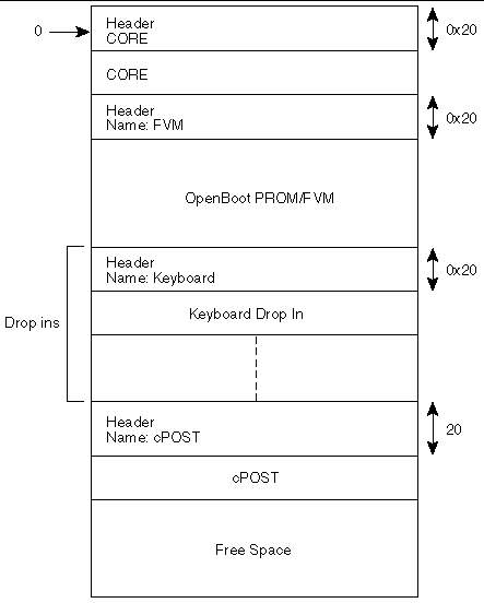
The node board boots from the 1 Mbyte system flash PROM device, which contains the firmware CORE, basic POST code, comprehensive POST, and OpenBoot PROM. The contents map of this PROM is shown in FIGURE 4-2.
User-developed code can also be programmed into the user flash memory space in the form of dropins. The system flash can be upgraded by running a program out of OpenBoot PROM--see Section 4.6, SMC Firmware. It is not otherwise accessible by the user.
The Netra CP2300 supports USB keyboards only.
Advanced System Monitoring (ASM) is an intelligent fault detection system to increase uptime and manageability at OpenBoot PROM. The SMC module on the Netra CP2300 board, supports the temperature monitoring functions of ASM. ASM monitors the following at regular intervals at the ok prompt:
|
Note - Refer to the Netra CP2300 cPSB Board Programming Guide (817-1331-xx) for additional information about the ASM features of the Netra CP2300 board. |
At the OpenBoot PROM level, when an over-temperature condition occurs, corresponding messages are displayed on the console. The OpenBoot PROM displays the warning messages as soon as the board temperature reaches the warning temperature and is still below the shutdown temperature. The shutdown messages are displayed as soon as the board temperature reaches the shutdown temperature. Finally, the critical messages are displayed when the board temperature reaches the critical temperature.
The warning-temperature, shutdown-temperature, and
critical-temperature are maintained in the SRAM for the Netra CP2300 board (for warning and shutdown temperature values, see TABLE 4-3). Also, the show-sensor command at OpenBoot PROM displays the readings of all the temperature sensors on the board.
When the CPU temperature reaches the set warning temperature limit, the following message is displayed at the ok prompt at regular intervals:
<<< !!! ALERT!!! Upper Non-critical - going high >>> The current threshold setting is: < > The current temperature is : < > |
When the CPU temperature reaches the set shutdown temperature limit, the following message is displayed at the ok prompt at regular intervals:
<<< !!! ALERT!!! Upper Critical - going high >>> The current threshold setting is: < > The current temperature is : < > |
The warning and shutdown temperature values provided are the OpenBoot PROM default values. A user can change these values by changing the corresponding SRAM variable values and resetting the system hardware or software.
ok setenv env-monitor enabled ok setenv warning-temperature <new_value>ok setenv shutdown-temperature <new_value> ok setenv critical-temperature <new_value>ok reset-all |
The <new_value> is a decimal value for a new temperature limit. The OpenBoot PROM then uses the new temperature limits after the system reset.
The field upgradeable SMC firmware supports features such as Netra CP2300 resources, temperature monitoring, control of the power subsystem, IPMI communication with other boards, configurable reset handling, hot-swap capability, and watchdog timer heartbeat mechanism. The SMC firmware also has its own built-in self-test at power up. The SMC consists of DS80CH11, which is an 8051 compatible chip and the PSD833F2 memory chip. Inside the PSD833F2 chip, there are the main flash and the boot flash and SRAM for data storage. The host CPU sends commands and data to SMC by way of the SBus. For more details on the SMC subsystem see Section 5.6, System Management Controller.
The SMC architecture allows the update of the SMC firmware. SMC firmware is only updated from the OpenBoot PROM. This feature is used to modify SMC firmware during a field upgrade, for fixing bugs, adding enhancements or new features, or providing special code for a specific OEM customer.
The SMC is capable of performing a flash update on the main and boot flash memory. The main flash can flash update the boot flash, and the boot flash can flash update the main flash. The boot code contains the minimum code to enable the system to boot to the ok prompt if the main flash fails, and to switch from boot flash to main flash for execution. Therefore, any attempt to perform a flash update of the boot flash would be considered risky and should not be done often.
The CORE/OpenBoot PROM code has support for recovery if the SMC flash update fails. When it detects that SMC is running from boot code, the code automatically goes to the ok prompt, enabling you to perform a flash update. Commands other than flash-update and get-version are not supported while running from the boot code.
The SMC power-on behavior and other attributes are stored in a 16-byte configuration block. This configuration block is stored in an accessible serial I2C SEEPROM. In the absence of this configuration block, SMC boots up in a default mode. At the OpenBoot PROM level, the setsmcenv and printsmcenv commands in the SMC node are used to set parameters in the configuration block of SMC. The printsmcenv command prints the value of the parameters in the SMC configuration block.
To view the settings on the configuration block, read the block using the printsmcenv command. If you want to change the settings, use the setsmcenv command to change the SEEPROM configuration block. Some examples are given in the code example below.
On the Netra CP2300 board, both the system (boot) flash and the user flash memory reside on the same physical device. By default the system flash uses 1 MByte of flash memory while the user flash uses 7 MBytes of flash memory (TABLE 4-4). For more information about system flash and user flash memory, see Section 5.3.4, Memory Components.
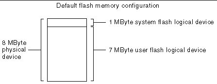
By default, the system flash is allocated 1 MByte of memory and user flash is allocated 7 MBytes of memory. If your application environment requires it, you can exchange these logical memory devices and make the system flash use 7 MBytes of memory and the user flash 1 MByte of memory.
To exchange these memory allocations, you must first change the SW3 DIP switch setting and set the flash-device setting in the configuration block. (See Section 4.6.1, SMC Configuration Block for more information about the configuration block.)
To Exchange the Flash Memory Devices:
1. At the ok prompt, use the printsmcenv command to display the configuration block.
If flash-device is set to any other value besides 4, you will need to set it to 4 in order to exchange the system flash and user flash memory allocations.
2. If the flash-device value is not equal to 4, use the setsmcenv command to set it to 4.
ok setsmcenv flash-device 4 |
3. Gracefully power-down the board and remove it from the chassis.
4. Locate the SW3 DIP Switch on the component side of the board.
The SW3 DIP switch is located slightly under the heat-sink on the board. FIGURE 4-4 shows the location and default setting of the SW3 DIP switch.
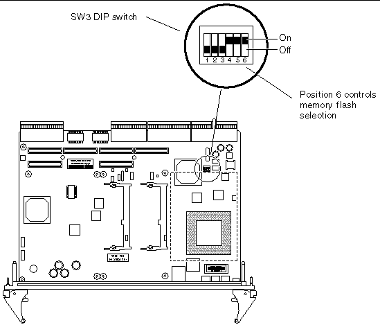
SW3 DIP switch position 6 controls the flash memory selection. When position 6 is set to on (default), system flash will be assigned 1 MByte of memory and user flash will be assigned 7 MBytes of memory.
When SW3 DIP switch position 6 is set to off, and the flash-device setting of the configuration block is set to 4, user flash will be assigned 1 MByte of memory and system flash will be assigned 7 MBytes of memory.
5. To set the flash memory selection, set the SW3 DIP switch position 6 to off.
See FIGURE 4-4 for the location of the SW3 DIP switch.
6. Re-install the Netra CP2300 board into the chassis or system.
See Chapter 2 for installation instructions.
7. Power on the Netra CP2300 board and display the OpenBoot PROM ok prompt.
After setting the DIP switch and the flash-device setting, the system flash will be assigned 7 MBytes of memory and the user flash will be assigned 1 MByte of memory (see FIGURE 4-5).
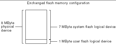
If you are unsure if system flash is allocated the default 1 MByte of memory or 7 MBytes of memory, you can use the OpenBoot devalias command to see where user flash logical device begins.
Using the devalias command at the ok prompt, you can see where the user flash device path begins. By default, the system flash will use 1 MByte of space, so the user flash will begin at 100000 bytes (0 to 99999 will be used by the system flash):
ok devalias uflash uflash /pci@1f,0/pci@1,1/isa@7/flashprom@1f,100000 |
If the SW3 DIP switch position 6 is set to off, and the flash-device is set to 4, the system flash uses 7 MBytes of space and the user flash device path will begin at 700000 (0 to 699999 will be used by the system flash):
ok devalias uflash uflash /pci@1f,0/pci@1,1/isa@7/flashprom@1f,700000 |
In both situations, the system flash device path will start at 0, so you should not use it to determine the flash memory sizes:
ok devalias flash flash /pci@1f,0/pci@1,1/isa@7/flashprom@1f,0 |
Use the flash-update and flat-update OpenBoot PROM commands to update the flash memory on the Netra CP2300 board. Use the flash-update command to update the Netra CP2300 board's OpenBoot PROM or add OpenBoot PROM drop-in packages, and use the flat-update command to add any raw device to flash memory.
flash-update file-path flashtype
flat-update file-path flashtype
Where file-path is the path to the flash update image, and flashtype can be:
You can only update the SMC firmware at the OpenBoot PROM ok prompt.
1. Contact your Field Application Engineer to acquire the updated SMC firmware image.
2. Save the firmware to a directory on the system.
3. Use the smc-flash-update command to update the SMC firmware:
ok smc-flash-update filename |
Replace filename with the filename and full path to the SMC firmware image.
|
Note - filename must point to a valid SMC firmware binary image or the file cannot be read to complete the flash update. |
The firmware contains a comprehensive set of hardware diagnostic modules that provide tests for most situations. FIGURE 4-1 shows the control-flow relationship of the diagnostic modules with the system firmware. SunVTS can be executed from within the Solaris software if more tests are required. For more information, see Section 3.3, Downloading and Installing SunVTS.
The firmware diagnostic modules are:
The firmware diagnostics cover address and data bits on all system buses and exercise the function of the major hardware resources on the board.
Diagnostics can be performed at OpenBoot PROM level by using the obdiag command, or by typing individual test commands at the ok prompt. These test suites are similar to those in earlier OpenBoot PROM versions but they are comprised of drop-ins that can be placed by the user. See the reference to the OpenBoot 4.x Command Reference Manual listed in Appendix D.
The user interface for running POST at minimum or maximum remains the same. BPOST is embedded within firmware CORE and is executed when the OpenBoot PROM environment variable, diag-switch? is set to true and diag-level is set to min. Similarly, CPOST (and EPOST if it is present) is executed when diag-level is set to max. The permutations are shown in TABLE 4-4.
CPOST and Extended POST are clients of firmware CORE.
BPOST is integrated into firmware CORE. The first part of BPOST executes from flash memory. It is designed to validate enough of the system resources to be able to run firmware CORE in main memory (system RAM). If this test phase is passed, BPOST is also copied into system RAM. BPOST runs when the diag-switch? is set to true (see TABLE 4-4).
The part of BPOST executed from flash includes basic tests for the following:
The second part of BPOST is performed after firmware CORE is copied into main RAM. This part of BASIC POST executed from RAM includes:
Comprehensive POST (CPOST) is a client of firmware CORE. It is a dropin module invoked by firmware CORE and contains enhanced diagnostics for the CPU and on-board devices.
The execution of CPOST is optional and can be selectively controlled by an environment variable (see TABLE 4-4). CPOST runs after BPOST. To run CPOST, set the environment variables diag-switch? to true and diag-level set to max
After CPOST the system undergoes a software reset which sends it back to firmware CORE. From this point, execution enters OpenBoot PROM (since diagnostics are only executed at power on reset).
The OpenBoot PROM on-board diagnostics reside in the OpenBoot PROM drop-in. These diagnostics are described fully in the OpenBoot 4.x Command Reference Manual (see Appendix D).
To execute the OpenBoot PROM on-board diagnostics, the system must be at the ok prompt. The OpenBoot PROM on-board diagnostics include:
The OpenBoot Diagnostics are an enhancement of the traditional system tests. They reside in Forth script in a drop-in and are invoked with an interactive tool that is started from the ok prompt by typing obdiag.
When you start the OpenBoot Diagnostics, you should see the following menu:
At the obdiag prompt, type test-all to display a printout similar to the following:
Copyright © 2003, Sun Microsystems, Inc. All rights reserved.