| C H A P T E R 1 |
|
Introduction |
Strong server-management capabilities are crucial to maintaining mission-critical servers. Advance notification of problems and rapid diagnosis and correction are critical functions to an environment in which a few servers bear the bulk of the workload. The Sun Fire V20z and Sun Fire V40z servers and their extensive server-management capabilities lower costs by reducing failure and by potentially eliminating hands-on management.
This document describes how to perform remote management on the Sun Fire V20z and Sun Fire V40z servers.
The Sun Fire V20z server is an AMD Opteron processor-based, enterprise-class one-rack-unit (1U), two-processor (2P) server. The Sun Fire V40z server is also an AMD Opteron processor-based server, but is a three-rack-unit (3U), four-processor (4P) server.
These servers include an embedded Service Processor (SP), flash memory, RAM, a separate Ethernet interface and server-management software. They come equipped with superior server-management tools for greater control and minimum total cost of ownership. You can use the command-line interface (CLI), SNMP integration with third-party frameworks, or IPMI to configure and manage the platform with the SP. The dedicated SP provides complete operating-system independence and maximum availability of server management.
TABLE 1-1 defines the acronyms found in this document.
There are several options for remotely managing a Sun Fire V20z or Sun Fire V40z server:
The Sun Fire V20z and Sun Fire V40z servers include a dedicated chipset for complete operating-system independence and maximum availability of server-management functions. This chipset, called Service Processor (SP), is an embedded PowerPC chip providing the following:
FIGURE 1-1 shows the back panel of the Sun Fire V20z server.
FIGURE 1-2 shows the back panel of the Sun Fire V40z server.
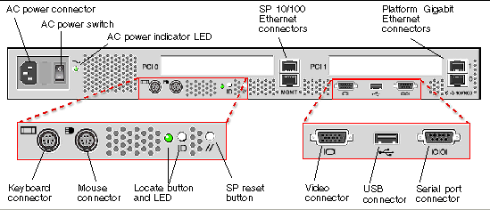
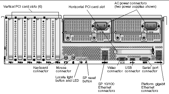
These servers include local and remote server-management capabilities through the SP; the SP supports four server-management interfaces:
Server-management capabilities are available from the command line.
See Appendix A for a list of server-management commands that you can use with these servers, as well as a description, the command format, a list of arguments and a list of return codes for each command.
A system administrator can log in to the Service Processor using SSH and issue commands, or more commonly, write a shell script that remotely invokes these operations.
The server-management commands enable you to efficiently manage each area of the server. From the command line, you can write data-driven scripts that automate the configuration of multiple machines. For example, a central management system can cause many servers to power on and boot at a specified time, or when a specific condition occurs.
For more information about scripting, see Further Management Information.
SNMP management provides remote access by SNMP-compliant entities to monitor the health and status of the server. The SP sends SNMP alerts to external management functions when warranted.
For more information about SNMP, refer to SNMP Server Management.
The diagram in FIGURE 1-3 illustrates the communications paths for the different server-management options.
You can use the operator panel to configure network settings for the SP. See FIGURE 1-4 or FIGURE 1-5 for the operator panel location on your server.
|
Note - The SP defaults to Dynamic Host Configuration Protocol (DHCP) networking if the operator panel is not interactively engaged on the first power-up. |
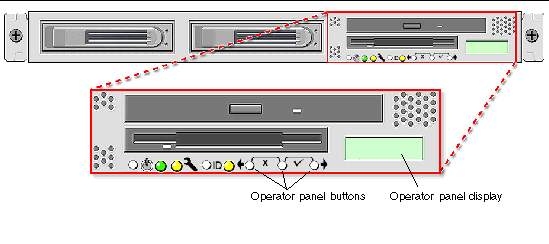
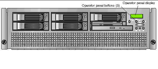
The operator panel displays information on the LCD display in two lines; you respond to prompts or initiate actions using the following buttons:
|
|
|
|
|
|
|
|
|
|
|
|
|
|
If a menu or data-entry screen displays for more than 30 seconds with no action taken, the menu or data entry is cancelled and the display returns to the idle/background state.
For every action that you confirm, feedback displays on the panel to indicate success, failure, or that the action has been initiated.
The Back and Forward buttons automatically scroll, repeating the action as long as the button is held down. After holding the button down a few seconds, auto scrolling begins and rapidly increments or decrements the value.
Administrators can define several different user groups, or types, on the server. Capabilities of the different user types are defined in TABLE 1-3.
For example, when you log in to the system the first time using the setup account, the first thing you must do is set up the initial manager account so that other user accounts can be managed. (see Creating the Initial Manager Account for details)
|
All capabilities except user account management and SP field upgrades |
|
This procedure describes the steps for the initial setup of the SP.
This section contains two alternate methods you can use to define SP network settings:
|
Note - As an alternative, if no DHCP server or physical access is available, you can configure the SP using IPMItool in conjunction with an IPMI kernel driver. To configure your server for IPMI, perform the correct procedures for your operating system in Part III: Enabling IPMI Access on the Server, then Part IV: Enabling IPMI LAN Access. |
The following procedure describes how to set the SP network settings using DHCP from the Operator Panel. If your network does not use DHCP, or you want to assign a static IP address to the SP, follow the instructions in Assigning Static SP Network Settings.
1. Press any operator panel button on the server front panel (see FIGURE 1-6).
The LCD panel displays the first menu option:

2. Press the Forward button until you reach the SP menu:
3. Press the Select button to display the SP menu options.
The following prompt appears with the default response:
5. Press the Forward button to change to Yes, then press the Select button.
6. Press the Select button at the confirmation prompt.
The server attempts to contact a DHCP server for an IP address. Once a DHCP server is contacted, the LCD panel displays the default SP settings. The SP address is configured and the server is ready for use.
7. Continue with Part II: Securing the Service Processor for instructions on creating the initial manager account.
|
Note - A prompt appears that asks if you want to perform autoconfiguration. As an alternative to configuring an SP manually, you can run autoconfiguration, which replicates the configuration of one SP to another. Refer to Autoconfiguring the SP (Optional Method)for instructions on autoconfiguration. |
Follow these steps to set the SP network settings using a static IP address. You must specify a subnet mask and default gateway. This example uses the following sample settings:
IP Address: 10.10.30.5
Subnet Mask: 255.255.255.0
Default Gateway: 10.10.30.254
1. Press any operator panel button on the server front panel (see FIGURE 1-6).
The LCD panel displays the first menu option:
2. Press the Forward operator panel button until you reach the SP menu:
3. Press the Select operator panel button to display the SP menu options.
4. Press the Select operator panel button. The following prompt displays with the default response:
5. Press the Select operator panel button.
6. With the cursor in the first field, increase or decrease the value using the Back and Forward operator panel buttons.
This field can hold a value between 0 and 255.
7. After reaching your desired value, press the Select operator panel button to advance the cursor to the next field.
|
Note - The Back and Forward operator panel buttons automatically scroll, repeating the action as long as the button is held down. |
8. Repeat Step 6 and Step 7 for each field until the desired IP address is displayed, then use the Enter button combination to save the IP Address.
The process continues to the next network setting, the Subnet Mask. The LCD displays as follows:
9. Edit the subnet mask setting in the same manner as you did for the IP address. When finished, use the Enter button combination to save the subnet mask.
The process continues to the next network setting, the default gateway. The LCD displays as follows:
10. Edit the default gateway setting in the same manner as you did for the IP address and the subnet mask. When finished, use the Enter button combination to save the default gateway.
The LCD displays the following confirmation prompt:
11. Press the Select operator panel button to use the new data, or use the Cancel button combination to disregard.
The SP address is now configured and the server is ready for use.
|
Note - A prompt appears that asks if you want to perform autoconfiguration. As an alternative to configuring an SP manually, you can run autoconfiguration, which replicates the configuration of one SP to another. Refer to Autoconfiguring the SP (Optional Method) for instructions on autoconfiguration. |
12. Continue with Part II: Securing the Service Processor.
After you install the server and configure the SP, you must create the initial manager account to secure and access the server. You can then perform initial configuration of the server and create additional user accounts.
A setup account is included with each server. This setup account has no password. When you log in to the SP the first time using the setup account, you are prompted to define the initial manager account with a password and an optional public key.
Log in to the setup account and create the initial manager account by following this procedure:
1. Using an SSHv1 or SSHv2 client, connect to the IP address of the SP.
2. Authenticate as the user setup with no password required.
3. Follow the on-screen prompts to create the initial manager account.
After you create the initial manager account, the setup account is deleted and you are logged out of the server. You can then log in using the new manager account, from which you can create other user accounts.
|
Note - The IP address, user name and password that you configure are referred to in subsequent examples as the spipaddr, spuser and sppasswd. |
This section contains two alternate procedures: one for a Linux-based server and one for a Solaris-based x86 server. Use the procedure that corresponds to your OS:
1. Log in to the server and authenticate as the user root.
2. Install the custom OpenIPMI Linux kernel driver from the Sun Fire V20z and Sun Fire V40z Servers Documentation and Support Files CD. The drivers are located in the CD directory /support/sysmgmt/.
Browse to the OS variant installed on your server. The options are:
3. Ensure that the kernel-source RPM is already installed on your distribution by running the command:
# rpm -qvi kernel-source
If this utility reports that the kernel-source software package is not installed, install the kernel-source RPM that is current for your installed Linux distribution.
# rpm -ivh /tmp/kernel-source*.rpm
4. Install the OpenIPMI Linux kernel driver RPM.
a. Browse to the OS variant installed on your server. The options are:
b. Install the OpenIPMI RPM file by running the command:
|
Note - The kernel driver will be compiled using the kernel-source code during installation. |
IPMItool is the command-line-interface (CLI) server-management client.
# rpm -ivh ipmitool*.x86_64.rpm
6. Test the IPMI kernel device driver and client application by running the following command:
# ipmitool -I open chassis status
Successful output should look similar to the following:
"
System Power: on
Power Overload: false
Power Interlock: inactive
Main Power Fault: false
Power Control Fault: false
Power Restore Policy: unknown
Last Power Event:
Chassis Intrusion: inactive
Front-Panel Lockout: inactive
Drive Fault: false
Cooling/Fan Fault: false
"
|
Note - On a subsequent reboot, the IPMI kernel driver may have to be loaded with the following command:
|
|
Note - If you upgrade your Linux kernel, refer to Upgrading the Linux Kernel. |
1. Log in to the server and authenticate as the user root.
2. Run the following command to install the LIPMI Solaris x86 kernel driver and the IPMItool management control application.
These files are located on the Documentation and Support Files CD in the /support/sysmgmt/solaris9 directory.
Confirm installation of all packages when prompted.
This section contains three alternate procedures: two in-band procedures and one out-of-band procedure. Use the procedure that corresponds to your OS:
1. If the server is powered off, boot the local OS.
2. Log in to the server and authenticate as the user root.
3. Load the OpenIPMI kernel device driver (as installed in Step 3 of Enabling IPMI Access on a Linux-Based Server (In-Band)).
# modprobe ipmi_kcs_drv
4. Using the following commands in IPMItool, configure the network setting for the SP.
|
Note - For more information on the syntax for IPMItool commands, refer to Syntax. |
# ipmitool -I open lan set 6 ipaddr ipaddr # ipmitool -I open lan set 6 netmask netmask # ipmitool -I open lan set 6 defgw ipaddr gwipaddr # ipmitool -I open lan set 6 password ipmipasswd
1. If the server is powered off, boot the local OS.
2. Log in to the server and authenticate as the user root.
3. Using IPMItool, configure the network setting for the SP by using the following commands.
|
Note - For more information on the syntax for IPMItool commands, refer to Syntax. |
# ipmitool -I lipmi lan set 6 ipaddr ipaddr # ipmitool -I lipmi lan set 6 netmask netmask # ipmitool -I lipmi lan set 6 defgw ipaddr gwipaddr # ipmitool -I lipmi lan set 6 password ipmipasswd
1. Using an SSHv1 client or SSHv2 client, log in to the IP address of the SP.
2. Authenticate as the newly created management user (see Part II: Securing the Service Processor").
# ssh spipaddr -l spuser
3. Enable IPMI LAN access and assign a password when prompted.
# ipmi enable channel lan # exit
|
Note - This password will be referred to as ipmipasswd in subsequent examples. |
4. Using IPMItool, test the IPMI LAN access.
# ipmitool -I lan -H spipaddr -P ipmipasswd chassis status
Upgrading the installed Linux kernel to a newer version requires you to recompile the upgraded IPMI kernel device driver.
1. Install the kernel-source RPM that matches the version of the upgraded kernel binary RPM package.
2. Log in to the server and authenticate as the user root.
3. Change to the following directory:
# cd /usr/src/kernel-modules/openipmi
4. Recompile the module by running the following commands:
# make clean # make # make install
5. Re-test the IPMI kernel device driver and client application by running the following command:
# ipmitool -I open chassis status
Successful output should look similar to the following:
"
System Power: on
Power Overload: false
Power Interlock: inactive
Main Power Fault: false
Power Control Fault: false
Power Restore Policy: unknown
Last Power Event:
Chassis Intrusion: inactive
Front-Panel Lockout: inactive
Drive Fault: false
Cooling/Fan Fault: false
"
|
Note - On a subsequent reboot, the IPMI kernel driver may have to be loaded with the following command:
|
You can interconnect multiple servers in a daisy-chain configuration by using the SP connectors to form a management LAN as shown in FIGURE 1-7. This figure also shows how the servers are connected to external LANs using the platform gigabit connectors.
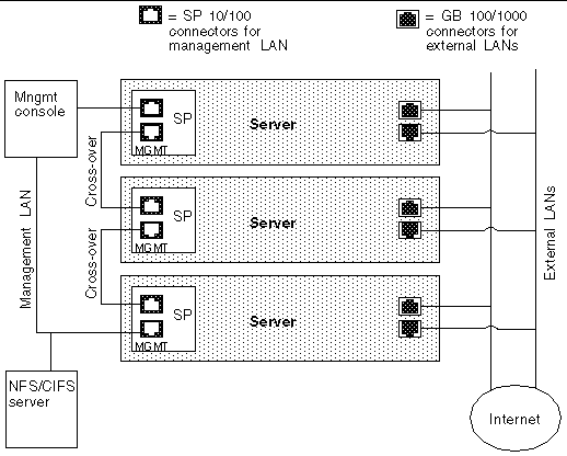
To interconnect the servers, you must use an RJ-45 cross-over cable. Cables can be connected to either the top or bottom SP port. To configure servers in a daisy chain, connect the first and last server in the chain to different switches.
Managed spanning-tree capable switches are required to redundantly connect both the top and bottom of the chain. If the switch is not capable of spanning-tree discovery, then only connect either to the top or the bottom of the chain, but not both.
When deploying your server, ensure that you determine the best integration strategy for your environment.
These servers include network connections for the service processor (SP) that are separate from network connections for the platform. This allows you to configure the server so that the SP is connected to an isolated, management network and is not accessible from the production network.
|
Note - For complete information about the menu options available through the operator panel, refer to the Sun Fire V20z and Sun Fire V40z Servers User Guide. |
If you attempt to update the SP software using the operator panel when the IP address for the SP has not been set, the update fails. Ensure that the IP address has been set prior to attempting an update. For more information, refer to the Sun Fire V20z and Sun Fire V40z Servers Installation Guide.
Refer to Operator Panel for general orientation and usage of the operator panel.
|
Note - Prior to executing this procedure, you must start the Java |
1. When the LCD displays the Service Processor information (as shown in the following example), press any button.
123.45.67.89 OS running
The LCD displays the first menu option:
Menu: Server Menu
2. Press the Forward button until you reach the SP menu.
Menu: SP menu
3. Press Select or Enter to display the SP menu's options.
SP Menu:Set SP IP info?
4. Press the Forward button until you reach the Update SP Flash menu option.
SP Menu: Update SP Flash?
6. A string of 0s displays with the cursor at the left digit. Use the Forward and Back buttons to increment or decrement a digit.
|
Note - You are prompted for an IP address. If you attempt to update the SP software using the operator panel when the IP address for the SP has not been set, the update fails. |
|
Note - If you need to supply a port address, it can be any number between 0 and 65535. The leading 0s are removed.
|
7. Press Select to move to the next digit.
8. Press Select when finished to return to the left-most column.
9. Press the button combination for Enter.
To update the SP base component:
1. Start the spupdate server on a machine with a Java Runtime Environment (JRE) by running the following command:
# java -jar spupdate.jar -f filename [ -p port ]
The spupdate.jar file is located in the spupdate folder of the Network Share Volume (NSV).
In this command, filename is an SP .image file located in sw_images/sp/spbase/version. This sw_images directory contains an SP base .image file for each version available.
By default, the server uses port number 52708. If this port number is already in use, specify another port using the optional -p flag.
The update server does not start if the file is not found in the specified path. Otherwise, the server is ready to receive update requests from any SP. The update server can simultaneously accept multiple update requests from different SPs.
2. Log in to the SP by running the following command:
# ssh spipaddr -l spuser
3. Run the sp command to start the update process on the SP:
# sp update flash all {-i | --ipaddress} IPADDRESS [{-p | --port} PORT]
Refer to Appendix A for more information about the sp commands.
4. Monitor progress of the update process on the server.
Messages display as the installation process progresses. When complete, the SP reboots with the new version installed.
Autoconfiguration replicates the majority of configuration files from an SP that has already been configured to another SP, so that the two servers have identical configurations, except for the host name and IP address.
For example, after you configure a single SP (set up users, hosts, certificates, mounts and so on), you then run autoconfiguration on each additional SP so that the settings are identical. In addition, if you modify the configuration of one SP, you can update all of them by re-running autoconfiguration on each one. (For this reason, set the IP address of the autoconfigure server to x.x.x.1.)
|
Note - Autoconfiguration does not merge configurations, it overwrites the existing configuration. |
|
Note - Autoconfiguration does not work across different server platforms. That is, you cannot configure a Sun Fire V40z service processor using settings on a Sun Fire V20z service processor. |
You can start autoconfiguration either when you are prompted at the completion of setting the IP address of the SP, or by selecting Autoconfigure from the SP menu option on the operator panel at any time.
To perform autoconfiguration of an SP, follow these steps:
1. On the operator panel, press the Forward or Back buttons until the following prompt shows Yes.
For instructions on setting an IP address, refer to the Sun Fire V20z and Sun Fire V40z Server Installation Guide.
The SP attempts to locate an IP address.
Where x.x.x is the first three octets of the SP IP address. For example, if the address is 10.10.30.19, the address that displays in the prompt appears as 10.10.30.1.
In this case, press the Select operator panel button to start autoconfiguration.
In this case, you must manually enter an IP address before you press the Select operator panel button to start autoconfiguration.
3. Wait until the autoconfiguration is complete, at which point the SP automatically reboots.
The following message displays when autoconfiguration is running.
|
Note - If the autoconfiguration is unsuccessful, a failure message displays. Press any button to clear it. |
Use the following commands if you need to determine the MAC address of your server's SP or platform:
# ssh spipaddress -l spusername sp get mac
# ssh spipaddress -l spusername platform get mac
Copyright © 2004, Sun Microsystems, Inc. All Rights Reserved.