| Sun StorEdge 3000 Family Configuration Service 1.5 User's Guide |
| Sun StorEdge 3000 Family Configuration Service 1.5 User's Guide |
| C H A P T E R 6 |
|
Monitoring the Array |
This chapter explains how to monitor the array using Sun StorEdge Configuration Service. It describes the main window and the component view windows that are available when an icon is double-clicked in the main window. It also explains how the Event Log works and how to use the reporting function. It is organized into the following sections:

|
Caution - Sun StorEdge Configuration Service can monitor and manage up to 32 arrays at one time. However, console response time can decrease as the number of arrays increases. |
The main window provides status at a glance for all array devices. It indicates the status of the devices and logical drives connected to servers monitored by the console. The devices include array controllers, disk storage enclosures, physical disk drives, and other SCSI devices.
This window's tree structure offers detail for all devices connected to each server. The  or
or  container symbol at the left side of the tree indicates whether the display of devices is expanded or collapsed. The
  container symbol means that you can click to display more devices. The
  container symbol indicates that all devices at and below that level are shown.
The following figure shows an example of the expanded view of the main window.
The following figure shows an example of a collapsed view.
For more information, you can double-click an icon to open a component view window. The component views are covered later in this chapter.
Another feature of the main window is that device states are color-coded and symbol-coded so that it is easy to identify when a device is in a state that requires attention. The status is propagated along the device tree, enabling you to trace a failure down to the device level. See TABLE 6-1 for device status details.
|
One or more components of this group or server are not working properly, but the array is still functional. For example, a logical drive that has one failed physical drive is operating in a degraded state. For the Sun StorEdge 3510 FC array, it might also indicate that the battery is going to expire in 21 days (see Battery Information for more information), or that the in-service date has not been set for a replacement battery. (Refer to the Sun StorEdge 3000 Family FRU Installation Guide for 2U Arrays for details on installing a replacement battery and To Verify the In-Service Date When Replacing a Battery for information on the in-service date.) |
||
|
One or more components of this group or server are not working. A logical drive with two failed disk drives or an enclosure with three failed fans would be in a critical state. For the Sun StorEdge 3510 FC array, it might also indicate that the battery has expired. (See Battery Information for more information.) |
||
To access online help, choose Help  Contents. The online help is in HTML format and depending on the OS, can be run through Microsoft Internet Explorer or Netscape Navigator
 . It includes information about major functions within the program.
For each server (or group of servers), devices in the tree view are arranged in a hierarchical order with the server (or group) at the top, followed by the array controllers. How the remaining devices -- logical drives, physical drives, and enclosures -- are shown might vary slightly, depending on which array and controller are being displayed. This section provides window views that might be depicted in the tree view.
A group is a logical collection of servers within the device tree. This new data object enables multiple servers to be contained under a single category.
The group object looks and behaves like all tree objects. It has an iconic representation and generally assumes the status of its servers. The following figure shows the group icon expanded to show the subordinate or underlying server objects.
A group is a new data object that enables multiple servers to be contained under a single category. Groups are similar in concept to domains. They enable you to organize servers. Instead of a linear tree of all the managed servers, you can organize the servers into like sets or groups.
Groups are color-coded and symbol-coded similarly to servers. States with their corresponding colors have the following order of precedence:
A server icon assumes the color of the highest state of any of its storage system. Likewise, a group icon takes on the highest state of any of its servers, with the following exceptions involving non responding or unlogged servers.
When a group icon is disabled (inactive), it indicates that all the servers attached to that group are not responding; if any number less than all of the servers in the group is not responding, the group icon appears red, representing a critical state. For example, if there are four servers in the group and three or fewer servers are not responding, the group icon is color-coded red.
When a group icon is color-coded white (not logged in), it indicates that one or more servers within that group have not yet been fully configured, or could represent a period of status transition. TABLE 6-2 gives an example of the different color coding of a two-server group.
Groups are not required. You can configure the program for no groups and fifteen servers, for example, or for one group with ten servers underneath, with an additional five at the top level. The program enables any combination.
The number of groups permitted and the number of servers within a group is limited only by available system memory. If a server is a member of a group and a user deletes that group from the group list box, servers are reassigned in that group to the no group category. The tree is remapped in the main window.
The console monitors storage devices on a network by communicating with an agent on the servers.
When the program is started, the console software begins by establishing contact with the agent on each managed server if Auto Discovery was specified when the server was configured. If Auto Discovery was not specified, you have to double-click each server and provide a password to start the discovery process for that server.
Establishing a TCP/IP connection between the console and the agent on each server and receiving back inventory information can take several minutes, depending on the complexity of the network. When this is occurring, the server icon in the main window displays a satellite dish icon on its right side. Once the inventory is refreshed, the satellite dish symbol is replaced by an active server symbol.
The agent on each server does a periodic scan of its inventory to check for changes. If there is a change, the agent sends an event to the console. Depending on the event, the console might request the inventory from that server's last scan to use for updating the representation of the server as displayed on the main window. During this process, the satellite dish icon is attached to the server icon, and you cannot do any configuration and array activity commands on that server until the refresh process is completed and the console main window is updated.
When the program is running and the server agent and console are connected, the agent pings or transmits a periodic signal to the console to verify the server's status. If the console does not receive a certain number of consecutive responses (handshakes) from the agent, the console marks the server as offline and disconnects from the server. The server's icon is made inactive and adjacently marked with a question mark symbol.
If a nonactive server was originally made active through the Auto Discovery function, the console periodically tries to reestablish server communications.
Occasionally, you might want to have an inventory performed on a server between the periodic status scans. To do this, double-click the server's icon to display the Server View window, and then click Rescan in that window.
If you have selected the Auto Discovery option (during the process of adding servers to the Managed Servers list, see Select or Deselect Automatic Discovery of servers:), the program automatically scans and performs an inventory on these servers. You are not required to provide a monitoring password to retrieve information provided by the program. Depending on the complexity of the network and the number of servers, it can take several minutes for the discovery process to finish.
However, if you choose not to use the Auto Discovery option on startup, the servers' icons are white, indicating that there is currently no information available for these servers. In this case, you need to double-click each server icon and specify the appropriate monitoring password.
You can also choose File Login. Once the password is specified for a server, the discovery process begins to perform an inventory on the selected server.
|
Note - If you need a very secure environment where access to server inventory data is restricted, select No for Auto Discovery (see Select or Deselect Automatic Discovery of servers:). |
Sun StorEdge Configuration Service provides detailed information about each agent or server and about the array devices that are connected to it. The fields on each of these views vary, depending on the capabilities of the disk controller.
Except for Save Report and View Report, which are located under the File menu, the commands and windows described in this section are accessed through the View menu.
View Group displays the servers that make up the group that is selected in the main
window.
To access View Group, double-click the group icon  in the main window or select the group icon and choose View View Group.
The Server List displays all servers that are attached to the specified group.
To view more information about any of the servers listed, select the appropriate status record in the list and click View, or double-click the status record. A window describing the corresponding server is displayed.
View Server displays the characteristics of the server that is selected in the main window.
To access View Server, double-click the server icon in the main window or select the server icon and choose View View Server.
|
Note - For SCSI and FC arrays, dual-port HBAs are displayed as separate entries because they have separate channels to which devices can be connected. |
Part of the TCP/IP network, the socket port makes a connection between the server and the client.
View HBA Card displays the characteristics of the Host Bus Adapter (HBA) card that is selected in the main Configuration Service window. It is only displayed when using out-of-band management.
To access View HBA Card, double-click the host adapter icon in the main Configuration Service window or select the host adapter icon and select View View HBA Card.
View HBA Card displays the status of the host adapter card and its device driver and provides a list of the devices connected to the adapter. Configuration Service channels start with number 0. The server listed at the top of the window is the server in which the host adapter is installed.
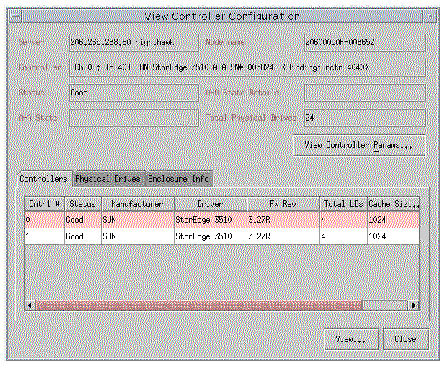
View Controller Configuration displays the components that make up the array.
To access View Controller Configuration, double-click the array icon in the main window, or select it and choose View View Controller.
The tabs at the bottom section of the window provide detailed information about the RAID controller's LUNs, on the physical drives attached to it, on the enclosure where the controller is located, and on the configuration of the peripherals. To bring the information for another tab into view, click the tab.
To access this window, double-click the array icon in the main window, or select it and choose View View Controller. Then click the Controller tab.
The Controller tab lists the controllers. To view more information about the controllers, double-click the desired controller or select the controller and click View. The SCSI and FC arrays have primary and secondary controllers. Depending on whether the controller is primary or secondary, the View Primary or View Secondary Controller Configuration window is displayed. See View Primary/Secondary Controller Configuration.
To access this window, double-click the array icon in the main window, or select it and choose View View Controller. Then click the Physical Drives tab.
The following figure shows the View Controller Configuration with the Physical Drives tab displayed.
The Physical Drives tab lists the physical drives associated with the array. To see details about any of the physical drives listed, double-click the drive or select the drive and click View. The View Physical Drive window is displayed. If a drive fails, the Scan SCSI Drive button is displayed.
For more information about View Physical Drive, see View Physical Drive.
To access this window, either double-click the Enclosure icon  in the main window, or select the array icon
  and choose View View Controller. Select the Enclosure Info tab. Select an enclosure and click View.
The information in the Enclosure Info tab includes the status of the power supplies, fans, battery, and the enclosure temperature. For more information about View Enclosure, see View Enclosure.
For the Sun StorEdge 3310 SCSI array only, to display the field-replaceable unit identification (FRU ID) information for the array, click View FRU. For example FRU ID information, see Double-click the enclosure icon..
Click View Controller Parameters to view detailed information about Channels, RS 232, Cache, Disk Array, Drive I/F, Host I/F, and Redundancy. To view the information, click the tab that corresponds to the item you want to view. To change controller parameters, see To Change Controller Parameters.
View Primary and View Secondary Controller Configuration windows display the characteristics of the controller that is selected in the main window. To display the primary controller characteristics, select the primary controller from the main window and choose View View Controller, or double-click the primary controller.
The following two examples show the primary controller.
The following two examples show the secondary controller.
To access this view window, double-click the primary or secondary controller icon in the main window, or select the controller icon
  and choose View Controller.
Click View Controller Params for editable component parameters on the RAID Controller Parameters window.
To view a logical drive, select and double-click a drive from the Logical Drives tab, or select a drive and click View.
View Logical Drive displays the characteristics of the logical drive that is selected in the main window.
To access this view window, use one of the following methods.
For more information about any of the disk drives listed, either double-click the drive's status record, or select the drive and click View. The View Physical Drive window is displayed.
View View Physical Drive presents the characteristics of the selected physical device. The title of the view window that appears varies, depending on the device selected.
You can access one of these windows by double-clicking the physical device in the main window, or by selecting the device and choosing View View Physical Drive.
You can also select the physical drive and select View. The View Logical Drive window is displayed without the table.
The View Tape and View CD-ROM windows are similar to that shown in the previous figure, but the categories differ slightly.
The View Enclosure window displays the component and alarm characteristics of an enclosure that is selected in the main window. (For SCSI, the EMU is identified by the name Sun StorEdge 3310 A; Id is always 14 or 15. For Fibre Channel, the SES is identified by the name Sun StorEdge 3510 A; Id is always the last Id within the enclosure in which the SES is contained.)
1. Select an EMU (SCSI array) or SES (Fibre Channel array) icon
2. Choose View View Enclosure.
The upper two sections of the window identify the enclosure and provide related information. Note that when there are multiple enclosures, you can use the Enclosure Number list box (located in the upper right corner of the window) to reflect another enclosure attached to the same controller.
For the 3510 FC array, to display battery information, click Battery and see Battery Information. To display the FRU IDs and information for all FRUs in the array, click View FRU and see View FRU.
The Alarm State section of the window applies only if you have an array with a SCSI Accessed Fault-Tolerant Enclosure (SAF-TE) (for a SCSI array) or SCSI Enclosure Services (SES) (for a Fibre Channel array) card.
|
Note - The Reset button on the View Enclosure window is reserved for future use. |
|
Note - Controller events can also cause an audible alarm. Pusing the Reset button has no effect on audible alarms caused by a controller event. See To Mute the Controller Beeper for information about muting the beeper. |
The lower section of the window provides status of the components in the window. When there is a device in the slot, it is represented by a drive icon with a color and a symbol representing its device state.
|
Note - The Battery Information window does not apply to the Sun StorEdge 3120 SCSI array or the Sun StorEdge 3310 SCSI array. |
In the event of a power failure, the battery maintains power to the cache for 72 hours. When power is restored, the data in cache is dumped to disk. For the Sun StorEdge 3510 FC array, Sun StorEdge Configuration Service monitors the usable life of the battery and displays its status in the Battery Information window. The program calculates the battery expiration date using the battery type, manufacture date, and in-service date, which have been programmed at the factory.
|
Note - For a battery FRU, you need to verify the in-service date so that Sun StorEdge Configuration Service can set it as explained in To Verify the In-Service Date When Replacing a Battery. |
The enclosure icon on the main window displays a degraded (yellow) status 21 days before the battery is going to expire. The enclosure icon also displays a warning (yellow) status if the in-service date has not been set for a battery FRU. A critical (red) status is displayed when a battery has expired. See Device Status State for device status symbols.
To view the battery status, choose View View Enclosure or double-click the enclosure. The View Enclosure window is displayed, showing the battery status in the Summary box.
To view battery information, including type, status, manufacture date, in-service date, and expiration date, click Battery. The Battery Information window is displayed.
When Sun StorEdge Configuration Service detects a battery FRU, the enclosure icon displays a degraded (yellow) status symbol as shown in the following example.
1. Double-click the enclosure icon.
Sun StorEdge Configuration Service calculates the battery expiration date using the in-service date (date that the battery is put into service), which is based on the host clock. The program prompts you to verify the date by displaying the following message:
2. If the host clock is correct, click Yes.
The following confirmation message is displayed. Click OK.
Sun StorEdge Configuration Service sets the in-service date and displays the date in the In-Service Date field in the Battery Information window.
3. If the host clock is incorrect, click No and reset the clock so that Sun StorEdge Configuration Service can prompt you to verify it again and set the in-service date.

|
Caution - If you do not reset and verify the in-service date, Sun StorEdge Configuration Service cannot accurately calculate the battery expiration date. |
A FRU is a field-replaceable unit. It is a part used to assemble a new system or to repair a system in the field. The Sun FRU ID (field-replaceable unit identification) program is a Sun solution for capturing, transmitting, and analyzing FRU-specific configuration, diagnosis, and failure information residing on the FRU.
Choose View View FRU to display the FRU IDs and information for all FRUs in the array including Serial Number, Model, Description, Vendor ID, Time (time the FRU was programmed), and Location.
Array Admin Progress displays the progress of new logical drive(s) initialization. This command is accessed by choosing View Array Admin Progress.
Agent Options enables you to customize the agent options, including polling time, periodic device discovery time, and SMART monitoring.
To access Agent Options, choose View Agent Options Management. For more information see, To Configure Agent Parameters.
The console receives, logs, and displays events generated by managed servers and by the console itself.
The majority of the events are generated by the agents on the managed servers and occur when there are:
Although array processes are initiated by the console, it is the server agent that generates operation notification events after these processes start on the server. For details about full event monitoring and email notification capabilities including sending email messages to a specified list when errors occur, see Email and SNMP.
The console generates a much smaller number of events. For example, it generates an event if it does not receive a certain number of consecutive heartbeats from a managed server.
When the console receives any event, it logs it in to the Event Log file, eventlog.txt, and displays it in the Event Log window. Also, if the event occurs on a server, the notification of the event is sent to that server's OS event log. On an NT server, it would go to the NT event log. In addition, when the event occurs on a server and that server is set up to send traps to an SNMP enterprise management console, such as HP OpenView, the server agent also sends a trap message to that computer.
Depending on the event received, the console might initiate a refresh process to request the inventory from the last periodic scan of the server involved, so the console can update the server's inventory on the main window.
During this refresh process, the satellite dish icon is attached to the server icon, and you cannot perform any configuration and array activity commands on that server until the process is completed and the main window is updated.
The Event Log window displays up to 500 events at a time. If you have more than 500 events, only the most recent 500 are displayed in the Event Log window; however, the program does not delete any events from the Event Log file, eventlog.txt, until more than 10,000 events have been logged.
|
Note - If the event log appears not to contain all of the events from the managed array, close and reopen the console. |
The events from the agent are logged into the system log of the host where the agent is installed, even if the console is not running. The following table lists the locations where the events are logged to in each OS.
|
The application log of the system, which can be viewed using Event Viewer. You can also read the event log directly from the file
|
|
For an IBM AIX OS, the event logs are not logged by default. You might need to change /etc/syslog.conf to enable it to write to a log file.
1. Modify /etc/syslog.conf to add the following line:
2. Make sure the file that is specified in the added line exists.
If it does not exist, you need to create it. For example, in the above configuration, you would create a file named /tmp/syslog.
3. Change to /tmp/syslog and restart the syslog by typing:
To access the Event Log window, choose View Event Log. You can hide this window by clicking Close. You can then reopen it (from the View menu) without losing any content.
The consoles begin to receive events when they are running, regardless of whether the Event Log window is open.
1. To delete the log file, click Delete Logfile.
The Confirmation window is displayed, prompting you to save the log file.
2. Select one of the following options:
The contents of the log file is deleted.
|
Note - You can also save and delete the contents of the eventlog.txt file using the Save Event Log and Delete Event Log icons on the toolbar. |
Each event record contains the fields shown in the following table.
You receive alarm forwarding for the level selected and any other levels of a higher severity. Thus, if you choose Informational, you are also notified of all alarm conditions. However, if you choose Critical, only Critical alarms are received.
For further information about messages, see Troubleshooting.
The Save Report option creates a text file containing all the information available to the program about a specific array.
The Report dialog box for confirming the server's ID is displayed. The Exportable to spreadsheets option enables you to save the report with delimiters (Comma, Semicolon, Tab, Colon, and Vertical Bar) for export to spreadsheets.
The Save Report File window is displayed.
3. Type a file name to identify the file and click Save.
The program writes the report on the inventory and status of the selected server and its devices.
The default save location for the report file is in the installation directory and the default file extension is .xml. It might be helpful to create a subdirectory for saving reports, so they do not clutter up the installation directory.
A report includes the following information:
The following excerpt is from an example report for a Sun StorEdge 3510 Fibre Channel array in .xml format, which can be used as input into another program.
Use the View Report option to review a report that was created.
The Open dialog box for selecting the report is displayed.
2. Select the report you want to review and click Open.
The out-of-band storage management capability enables you to monitor and manage arrays over the network using TCP/IP. Unlike in-band storage management (the standard method of storage management for storage), which requires the agent to be running on the server that is physically attached to the storage, out-of-band storage management does not require the agent to be running on the server that is physically attached to the storage. With out-of-band storage management, if the server that is attached to the storage is shut down, monitoring and maintenance is unaffected.
The following figures show examples of in-band and out-of-band storage management configurations.

For more information about configuring your array for out-of-band management, see Email and SNMP.

|
Note - Controller, SAF-TE, and Drive firmware cannot be upgraded through out-of-band management. |
1. Make sure you have set up a static or dynamic IP address for the array.
If the program has been configured already to manage the array through in-band, you can set the IP address through Change Controller Parameters. To set the IP address, see Network Tab. If the program has not been configured yet, you can set the IP address through an RS-232 terminal. Refer to the Sun StorEdge 3000 Family Installation, Operation, and Service Manual for your array.
2. After setting the IP address, reset the controller.
Choose Array Administration Controller Maintenance, and then click Issue Reset to the Controller.
4. Select View Agent Options Management.
5. In the Agent Options Management window, check Out-Of-Band Agent preferred over In-Band.
6. Type the IP address of the array in the IP Address field, and click Add.
7. If you have created a password for the array using the firmware application, type it in the Password field, and then re-type it in the Verify Password field.
|
Note - By default there is no password set for the array. For information on creating or changing the password, refer to the Sun StorEdge 3000 Family RAID Firmware User's Guide for your array. |
8. For the program to recognize the out-of-band array and display it in the main window, select the server.
11. If the program has not been configured to manage the array, you need to assign the server to manage the controller.
Choose Array Administration Controller Assignment. Select a server from the Server to manage this controller list and click Apply.
An out-of-band HBA is displayed in the main window and View HBA Card is displayed in the Menu Bar under the View menu.
|
Note - If an out -of-band HBA is not displayed in the window, reset the controller. |
2. Choose View Agent Options Management.
3. Select the array you want to remove from the Managed Primary Agent list, and click Remove.
The HBA remains displayed in the main window; to remove it, you need to stop/restart services.
The web-based storage management capability enables you to conveniently manage the array through the web without having to load the entire Sun StorEdge Configuration Service package. The following steps describe how to set up the array for web-based management and how to access it through a web browser.
Sun StorEdge Enterprise Storage Manager Topology Reporter can be viewed through a URL on any machine connected to the same network (you must have an account on the Solaris host machine).
|
Note - For the IBM AIX OS, Java Plug-in software versions earlier than 1.3 are not supported. |
Although the entire Sun StorEdge Configuration Service package isn't required to be loaded on the machine that is going to be used to access the array from the web, a few program files are needed; therefore, the entire Sun StorEdge Configuration Service package must be installed on another server so you can transfer files from it to the array. The following procedure describes how to conveniently transfer the necessary files to set up web management.
1. Make sure you have an Ethernet connection from the network to the array and you have established an IP address for it.
2. From the server that has the entire Sun StorEdge Configuration Service package installed, choose Configuration Custom Configure.
3. Select Configure Web Server.
4. Verify the IP address of the managing agent, which is the agent that is running on the server directly connected to the storage.
5. Enter the IP address of the array where the files are going to be transferred and click OK.
After the files are transferred successfully, a confirmation message is displayed, and the console can now be accessed through the web.
2. Type the following URL address:
3. Continue monitoring, maintaining, and updating storage as explained in the applicable chapters in this guide.
| Sun StorEdge 3000 Family Configuration Service 1.5 User's Guide | 817-3337-12 |
Copyright © 2004, Sun Microsystems, Inc. All rights reserved.


 in the main window.
 select a logical drive in the list box, and click View.

 , it is called View Physical Drive window.
 , it is called View Tape window.
 , it is called View CD-ROM window.


 To Verify the In-Service Date When Replacing a Battery


