| C H A P T E R 3 |
|
Removing and Replacing Front and Rear Panel Components |

|
Caution - The procedures in this section are for qualified service engineers only. |

|
Caution - Before carrying out any of the procedures in this chapter, read Avoiding Electrostatic Discharge, and wear a properly grounded antistatic strap. |
|
Note - Illustrations might contain optional components that are not available on all standard configurations of the Netra 240 server. |
This chapter gives removal and replacement procedures for the following components:
The bezel assembly includes the bezel, the server status indicator board, the alarm LEDs, and the hinges (FIGURE 3-1). The assembly is replaced as a single unit.
2. Ensure that the server is properly grounded.
See Avoiding Electrostatic Discharge.
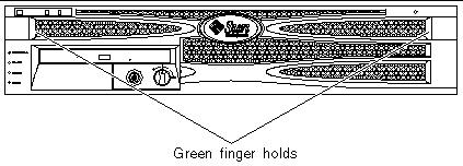
3. Grip the bezel at the two finger holds and rotate it down to its open position (FIGURE 3-1).
4. Disconnect the bezel cables (the server status indicator cable and the alarm LED cable) connecting the bezel assembly to the server (FIGURE 3-2).
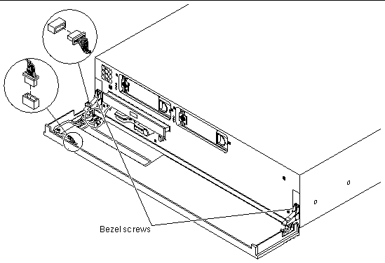
5. Unscrew and remove the bezel screws from the bezel hinges.
6. Lift and pull the bezel forward to remove it from the server.
1. Mount the new bezel and hinges onto the server.
2. Secure the bezel assembly to the server using the screws.
3. Reconnect the bezel cables (FIGURE 3-2).
The air filter is fitted on the inside of the Netra 240 bezel.
1. Ensure that the server is properly grounded.
See Avoiding Electrostatic Discharge.
2. Grip the bezel at the two finger holds and rotate it down to its open position (FIGURE 3-1).
3. Lift out the air filter from the inside of the bezel by gripping it near the DVD bay area (FIGURE 3-3).
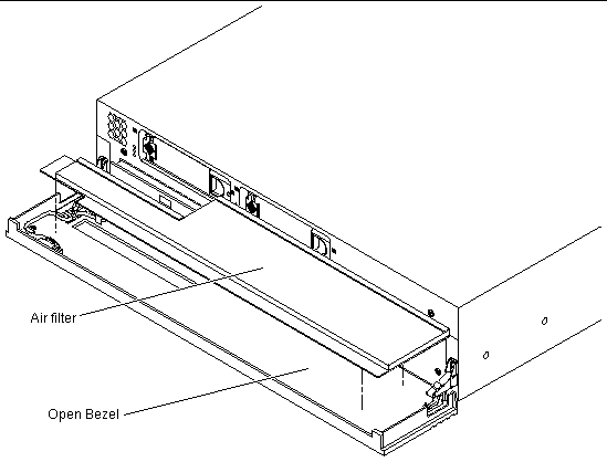
1. Snap the new air filter into place in the bezel (FIGURE 3-3).
The system configuration card (SCC) ships tied in place to prevent the card from getting lost. The SCC contains a server's unique network identity information, including the MAC address and host ID (stored in the IDPROM), and the OpenBoot PROM configuration (also known as NVRAM). For more on the NVRAM, see Appendix C.
You can use the procedures in this section to either replace a faulty SCC or to swap a server's unique configuration information from one server to another.
If the system configuration card is faulty or lost, a replacement card can be obtained from Sun Services. See Appendix A for the system configuration card part number. For more information on how to contact Sun Services, read the Netra 240 Server Release Notes (817-3142).
The replacement system configuration card is not programmed with any OpenBoot PROM and ALOM configurations. Upon initial insertion in the Netra 240 server, you are prompted for confirmation that you wish to use the new card. It is then configured with the default configuration for the server.

|
Caution - Avoid contact with the gold terminals on the underside of the card. |
See Powering Off the Server. If you are swapping configuration information from one server to another, you must power off both servers before proceeding.
2. Open the front bezel (FIGURE 3-1).
3. Cut and remove the tie wrap that secures the system configuration card, and remove the card from the system configuration card reader (FIGURE 3-4).
|
Note - Once the system configuration card is inserted into the system configuration card reader, secure a new tie wrap to discourage accidental or unintentional removal of the card. |
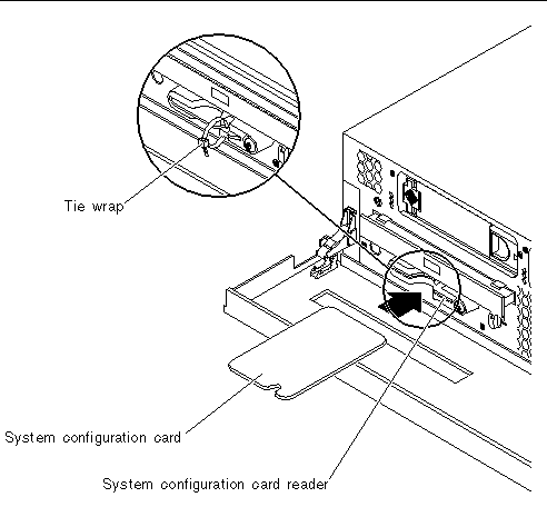
1. Insert the system configuration card into the system configuration card reader (FIGURE 3-4).
2. Replace the tie wrap on the card.
|
Note - By replacing the tie wrap, you ensure that the system configuration card is properly seated in the card reader (see FIGURE 3-4). If the card projects out of the card reader, the system does not boot properly. The tie wrap discourages accidental or unintentional removal of the system configuration card. |
The Netra 240 server has slots for up to two internal hard drives. The slots accept any Sun Low Voltage Differential (LVD) SCSI hard drive conforming to the 1-inch SCA-2 form factor.
If you are removing a hard drive while the operating system is still running, you must remove the drive logically from the operating system before physically removing it from the server. If you are removing a hard drive from a server that is powered off, skip to Step 6 in these procedures.
Use the following instructions in conjunction with the cfgadm(M) man page.
1. Check that the hard drive you want to remove is visible to the operating system.
2. Determine the correct Ap_Id label for the hard drive that you want to remove.
3. Unconfigure the hard drive that you intend to remove.
Use the unconfigure command and specify the device you intend to remove. For example, if it is Disk 1, type:
4. Check that the device is now unconfigured:
5. Confirm that the hard drive you want to remove from the server is no longer visible to the operating system:
# format Searching for disks...done AVAILABLE DISK SELECTIONS: 0. c1t0d0 <SUN72G cyl 14087 alt 2 hd 24 sec 424> /pci@1c,600000/scsi@2/sd@0,0 Specify disk (enter its number): |
6. Ensure that the server is properly grounded.
See Avoiding Electrostatic Discharge.
7. Grip the bezel at the two finger holds and rotate it down to open (FIGURE 3-1).
8. Check that the blue indicator LED is lit on the hard drive.
The blue LED comes on when the hard drive is ready to remove. See FIGURE 1-6 for the location of the LED indicators for the hard drive.
9. Slide the catch at the front of the hard drive to the right (FIGURE 3-5).
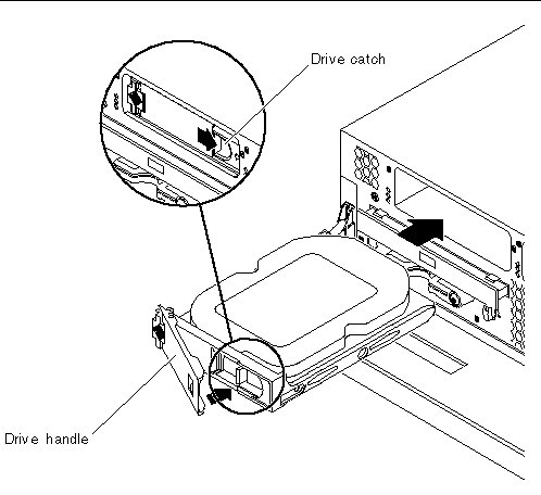
10. Pull the handle and remove the hard drive from the server by sliding it out from its bay.
1. Slide the catch on the front of the hard drive to the right (FIGURE 3-5).
This releases the handle on the front of the hard drive. The lever must be open before you insert the hard drive into the server. If the lever is closed, the hard drive will not engage with the server correctly.
2. Slide the hard drive into its bay at the front of the server.
Push the drive in firmly until the metal lever starts to close. This indicates that the hard drive has engaged with its connector in the server.
3. Push the metal lever until the drive clicks into place.
5. Determine if the server is powered off or not.
6. Log into the system as superuser and run the format command so that the drive is visible to the operating system.
Type the following command. (The typical output shown is from a system containing two hard drives.)
7. Determine the label of the new hard drive.
The label appears in the Ap_Id column of the sample output. Type:
In the preceding sample output, the new drive is Disk 1.
8. Connect the new drive logically to the operating system.
Type the following command, specifying the correct Ap_Id label for the drive you have installed (in this sample command the Ap_Id label is for Disk 1):
9. Confirm that the drive is now connected and configured:
The drive is now available to be mounted for operation.
The DVD drive is not hot-swappable. Before you can remove or insert an optional DVD-ROM drive or an optional DVD-RW drive, the server must be powered down and the power input cables disconnected from the rear of the server.
2. Grip the bezel at the two finger holds and rotate it down to open (FIGURE 3-1).
3. Unclip the catches that fasten the DVD drive to the chassis (FIGURE 3-6).
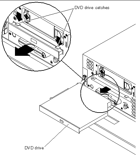
4. Pull the DVD drive toward you until it is free of its connectors and out of the server.
1. If the server is powered on, power off the server.
2. If a filler panel is installed, remove the filler panel from the DVD drive slot by pulling it towards you (FIGURE 3-7).
|
Note - Retain the DVD drive slot filler panel for future use. |
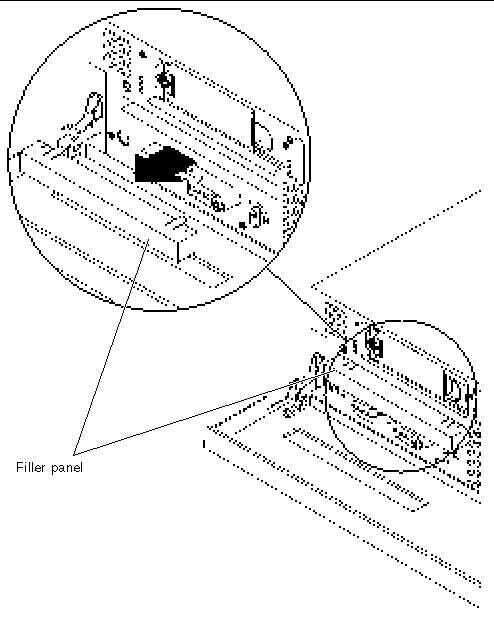
3. Push the DVD drive firmly into the drive slot until the DVD connector is inserted into the system and the clips engage with the chassis (FIGURE 3-6).
The Netra 240 server has dual redundant power supplies. You can hot-swap one power supply while the other is still running, without having to power off the server.
Where n is the power supply unit identifier (1 or 2). For example, to replace power supply unit 1, you would enter:
When the blue OK to Remove LED on the back of the power supply unit lights up, you can safely remove the unit. See FIGURE 1-7 for the location of the LED indicators for the power supply unit.
2. Disconnect the power input cable from the power supply unit being replaced.

|
Caution - Do not remove the power input cable from the remaining power supply unit. Doing so causes the system to go through an immediate ungraceful shutdown. |
3. Pull the lever on the back of the power supply unit down (FIGURE 3-8).
This disconnects the power supply unit from the power distribution board inside the server.
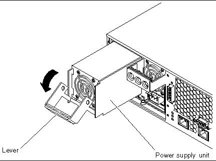
4. Slide the power supply unit out of the server chassis by pulling on the lever (FIGURE 3-8).
1. Insert the power supply unit in the power supply unit bay.
2. Slide the power supply unit into the server until you feel it engage with the power distribution board inside.
Ensure that the lever does not return to a vertical position until the power supply unit engages with the power distribution board. If the lever is vertical, the power supply unit does not engage correctly.
3. Press the lever up until it clicks.
Returning the lever to a vertical position engages the power supply unit with the power distribution board inside the server.
Where n is the power supply unit identifier (0 or 1). For example, to power on power supply unit 1, you would type:
5. Use the power supply unit LED indicators to verify that the power supply unit is up and running.
The green LED on the back of the power supply unit should light up, indicating that the power supply unit is functioning properly. See FIGURE 1-7 for the location of the LED indicators for the power supply unit. If the green LED on the back of the power supply unit does not light up, repeat Step 1 to Step 5.
Copyright © 2004, Sun Microsystems, Inc. All rights reserved.