C H A P T E R  4

Connecting the Data Cables

This chapter provides the data cabling instructions for the Netra 240 server, and contains the following sections:


Note - See Chapter 5 for a listing of the power site requirements and the instructions for assembling and connecting the power cables.


Rear Cable Connections

FIGURE 4-1 displays the location of the rear cable connectors of the DC server, FIGURE 4-2 displays the AC server's rear cable connectors, and TABLE 4-1 describes these connectors.
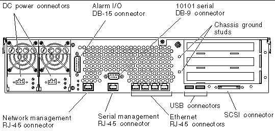
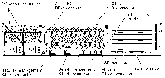
  FIGURE 4-1 Rear Cable Connectors (DC Server)

Figure showing the cable connectors on the rear of the server.

  FIGURE 4-2 Rear Cable Connectors (AC Server)


TABLE 4-1 Rear Cable Connector Descriptions

Cable Connector

Connector Type

Description

DC power
(DC server only)

WAGO

DC power input cables connect to each DC connector. Do not connect the power cables to a DC connector at this point.

Note: See Chapter 5 for instructions on assembling and connecting the DC power cables.

AC power
(AC server only)

IEC320

AC power input cables connect to each AC connector. Do not connect the power cables to a AC connector at this point.

Note: See Chapter 5 for instructions on assembling and connecting the AC power cables.

Alarm I/O

DB-15

In a telecommunications environment, use this port to connect to the central office alarming system.

10101 serial

DB-9

Use this serial port for general purpose data transfer.

Chassis ground studs

Two exposed studs

Use these studs to connect the server to protected earth ground.

Network management

RJ-45

Use this port for making an Ethernet connection to the ALOM software.

Serial management

RJ-45

Use this serial port for server management using the ALOM software.

Ethernet

Four RJ-45

Use these ports to connect to autonegotiating 10/100/1000BASE-T Ethernet networks.

USB

Two USB

Use these two ports to connect to external USB 1.1 devices.

SCSI

68-pin Ultra160 LVD

Use this port to connect to external SCSI devices.


Connecting the Chassis Grounding Cable

Before installing any other cable, you should first attach the chassis ground cable to the server's chassis grounding studs. Refer to the Chapter 5 for the site requirements for this section.

1. Obtain a chassis grounding cable from your site and two M5 nuts with lock washers from the ship kit.

2. Go to the back of the server and locate the two chassis grounding studs (see FIGURE 4-3).

3. Position and align the chassis grounding cable against the two grounding studs at the rear of the chassis.
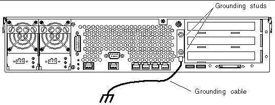
  FIGURE 4-3 Location of Chassis Grounding Studs

Figure showing the location of the grounding studs and where to connect the grounding cable.

4. Tighten the two M5 nuts to secure the grounding cable to the two studs.

5. Secure the other end of the grounding cable to the earth ground in the building.

You can secure the grounding cable to a proper grounding point on the rack, as long as the rack is properly grounded to the earth ground in the building.


caution icon

Caution - An electrical hazard is present if energized units are not properly grounded.


Connecting the Data Cables

This section provides information about the rear panel cable connections.


Note - See Chapter 5 for complete information about assembling and connecting the power cables.


Gigabit Ethernet Ports

The Netra 240 server has four autonegotiating 10/100/1000BASE-T Gigabit Ethernet system domain ports. All four Ethernet ports use a standard RJ-45 connector, the transfer rates for which are given in TABLE 4-2. FIGURE 4-4 shows the pin numbering of the ports, and TABLE 4-3 describes the pin signals.

TABLE 4-2 Ethernet Connection Transfer Rates

Connection Type

IEEE Terminology

Transfer Rate

Ethernet

10BASE-T

10 Mbit/s

Fast Ethernet

100BASE-TX

100 Mbits/s

Gigabit Ethernet

1000BASE-T

1000 Mbit/s


  FIGURE 4-4 Gigabit Ethernet Port Pin Numbering

Figure showing RJ-45 Ethernet connector pin locations.
TABLE 4-3 Gigabit Ethernet Port Signals

Pin

Signal Description

Pin

Signal Description

1

Transmit/Receive Data 0 +

5

Transmit/Receive Data 2 -

2

Transmit/Receive Data 0 -

6

Transmit/Receive Data 1 -

3

Transmit/Receive Data 1 +

7

Transmit/Receive Data 3 +

4

Transmit/Receive Data 2 +

8

Transmit/Receive Data 3 -


Network Management Port

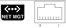
The server has one 10BASE-T Ethernet management domain interface, labelled NET MGT. For information on configuring this port for managing the server with ALOM, see the Sun Advanced Lights Out Manager User Guide for the Netra 240 Server
(
817-3174).


caution icon

Caution - If you are planning to use the network management (NET MGT) port, you must use a shielded Ethernet cable to maintain your server's NEBS compliance. The cable's shield must be grounded at both ends.


  FIGURE 4-5 Network Management Port Pin Numbering

Figure showing the RJ-45 network management port pin numbering.


TABLE 4-4 Network Management Connector Signals

Pin

Signal Description

Pin

Signal Description

1

Transmit Data +

5

Common Mode Termination

2

Transmit Data -

6

Receive Data -

3

Receive Data +

7

Common Mode Termination

4

Common Mode Termination

8

Common Mode Termination


Serial Ports

The server has two serial ports, labeled SERIAL MGT and 10101. TABLE 4-5 lists the default serial connection settings for both serial ports.

TABLE 4-5 Default Serial Connection Settings

Parameter

Setting

Connector

SERIAL MGT or 10101

Rate

9600 baud

Parity

None

Stop bits

1

Data bits

8


Serial Management Port

The serial management connector (labeled SERIAL MGT) is an RJ-45 connector that can be accessed from the back panel. This port is the default connection to the system, and you should use this port only for server management.


caution icon

Caution - You must use a shielded Ethernet cable to maintain your server's NEBS compliance. The cable's shield must be grounded at both ends.


FIGURE 4-6 shows the pin numbering of the serial management port, and TABLE 4-6 describes the pin signals.
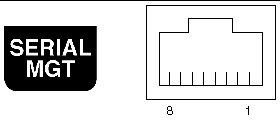
  FIGURE 4-6 Serial Management Port Pin Numbering

Figure showing the RJ-45 serial management port pin numbering.
TABLE 4-6 Serial Management RJ-45 Connector Signals

Pin

Signal Description

Pin

Signal Description

1

Request to Send

5

Ground

2

Data Terminal Ready

6

Receive Data

3

Transmit Data

7

Data Set Ready

4

Ground

8

Clear to Send


If you need to connect to the SERIAL MGT port using a cable with either a DB-9 or a DB-25 connector, use a supplied adapter to perform the crossovers given for each connector. The supplied RJ-45 to DB-9 and RJ-45 to DB-25 adapters are wired as described in TABLE 4-7 and TABLE 4-8.

RJ-45 to DB-9 Adapter Crossovers
TABLE 4-7 RJ-45 to DB-9 Adapter Crossovers

Serial Port (RJ-45 Connector)

DB-9 Adapter

Pin

Signal Description

Pin

Signal Description

1

RTS

8

CTS

2

DTR

6

DSR

3

TXD

2

RXD

4

Signal Ground

5

Signal Ground

5

Signal Ground

5

Signal Ground

6

RXD

3

TXD

7

DSR

4

DTR

8

CTS

7

RTS


RJ-45 to DB-25 Adapter Crossovers
TABLE 4-8 RJ-45 to DB-25 Adapter Crossovers

Serial Port (RJ-45 Connector)

DB-25 Adapter

Pin

Signal Description

Pin

Signal Description

1

RTS

5

CTS

2

DTR

6

DSR

3

TXD

3

RXD

4

Signal Ground

7

Signal Ground

5

Signal Ground

7

Signal Ground

6

RXD

2

TXD

7

DSR

20

DTR

8

CTS

4

RTS


Serial Port (10101)

The port labeled 10101 accepts a DB-9 connector. Use this port for general purpose serial data transfers. FIGURE 4-7 shows the pin numbering of the serial port, and TABLE 4-9 describes the pin signals.

  FIGURE 4-7 Serial Port (10101) Pin Numbering

Figure showing the serial port (10101) pin numbering.


TABLE 4-9 Serial Port (10101) Connector Signals

Pin

Signal Description

Pin

Signal Description

1

Data Carrier Detect

6

Data Set Ready

2

Receive Data

7

Request to Send

3

Transmit Data

8

Clear to Send

4

Data Terminal Ready

9

Ring Indicate

5

Ground


Alarm Port

The alarm port on the alarm rear transition card uses a standard DB-15 male connector. In a telecommunications environment, use this port to connect to the central office alarming system. FIGURE 4-8 shows the pin numbering of the alarm port, and TABLE 4-10 describes the pin signals.
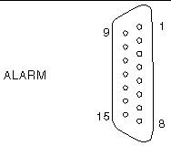
  FIGURE 4-8 Alarm Port Pin Numbering

Figure showing alarm port pin numbering.
TABLE 4-10 Alarm Connector Signals

Pin

Service

Pin

Service

1

INPUT0 +

9

ALARM1_NC

2

INPUT0 -

10

ALARM1_COM

3

NC

11

ALARM2_NO

4

NC

12

ALARM2_NC

5

ALARM0_NC[1]

13

ALARM2_COM

6

ALARM0_NO*

14

ALARM3_NO

7

ALARM0_COM*

15

ALARM3_COM

8

ALARM1_NO

CHASSIS

FRAME GND


USB Ports

The server has two USB ports for attaching supported USB 1.1-compliant devices. FIGURE 4-9 shows the pin numbering of the USB ports, and TABLE 4-11 describes the pin signals.

  FIGURE 4-9 USB Ports Pin Numbering

Figure showing USB port pin numbering.


TABLE 4-11 USB Connector Pin Signals

Pin

Signal Description

1

+5 V

2

DAT-

3

DAT+

4

Ground


SCSI Port

The SCSI port is a multimode Ultra 160SCSI interface. To operate at Ultra 160SCSI speeds, the part must be in Low-Voltage Differential (LVD) mode. If a single-ended device is connected to the server, it automatically switches to single-ended mode. FIGURE 4-10 shows the pin numbering of the SCSI port, and TABLE 4-12 describes the pin signals.

  FIGURE 4-10 SCSI Port Pin Numbering

Figure showing SCSI port pin numbering.
TABLE 4-12 SCSI Port Pin Signals

Pin

Signal Description

Pin

Signal Description

1

Data12 +

35

Data12 -

2

Data13 +

36

Data13 -

3

Data14 +

37

Data14 -

4

Data15 +

38

Data15 -

5

Parity1 +

39

Parity1 -

6

Data0 +

40

Data0 -

7

Data1 +

41

Data1 -

8

Data2 +

42

Data2 -

9

Data3 +

43

Data3 -

10

Data4 +

44

Data4 -

11

Data5 +

45

Data5 -

12

Data6 +

46

Data6 -

13

Data7 +

47

Data7 -

14

Parity0 +

48

Parity0 -

15

Ground

49

Ground

16

DIFF_SENSE

50

Ground

17

TERM_PWR

51

TERM_PWR

18

TERM_PWR

52

TERM_PWR

19

(N/C)

53

(N/C)

20

Ground

54

Ground

21

ATN +

55

ATN -

22

Ground

56

Ground

23

BSY +

57

BSY -

24

ACK +

58

ACK -

25

RST +

59

RST -

26

MSG +

60

MSG -

27

SEL +

61

SEL -

28

CD +

62

CD -

29

REQ +

63

REQ -

30

I/O +

64

I/O -

31

Data8 +

65

Data8 -

32

Data9 +

66

Data9 -

33

Data10 +

67

Data10 -

34

Data11 +

68

Data11 -


1 (TableFootnote) The ALOM software sets the ALARM0 (critical) relay and the associated (critical) LED for the following conditions:
bullet When the system is in Standby mode.
bullet When the server is powered on and the operating system has not booted or has failed.