| C H A P T E R 5 |
|
Power Source Requirements and Connections |
This chapter describes the power source requirements for the Netra 240 server and how to assemble and connect the power cables. This chapter contains the following sections:
|
Note - If you are installing a DC-powered version of the Netra 240 server, go to DC Source Site Requirements and Assembling and Connecting the DC Input Power Cable for instructions. For instructions for the
|
TABLE 5-1 gives operating power limits for the DC version of the Netra 240 server, and TABLE 5-2 provides the limits for the AC version of the server.
TABLE 5-3 shows the estimated power consumed in a fully populated, DC-powered Netra 240 server. TABLE 5-4 shows the estimated power consumed in a AC-powered server.
|
(with a DVD-ROM, hardware cryptographic module, and three PCI cards) |
|
|
(with a DVD-ROM, hardware cryptographic module, and three PCI cards) |
|
(with a DVD-ROM, hardware cryptographic module, and three PCI cards) |
|
|
(with a DVD-ROM, hardware cryptographic module, and three PCI cards) |
|
Note - The maximum input power values shown in TABLE 5-4 are based on AC power supply efficiency. |
|
Note - For more information about server configurations, and to see a list of optional components, refer to the SunStore web site (http://store.sun.com). |
Details of the power source requirements for the Netra 240 server are provided in this section.
|
Note - Depending on the DC power source, the -48V (negative terminal) might be marked with a minus (-) symbol, and the -48V Return (positive terminal) might be marked with a positive (+) symbol. |
|
Note - Overcurrent protection devices must meet applicable national and local electrical safety codes and be approved for the intended application. |
This section describes how to assemble and connect the DC input power cable and the location of the I/O ports at the rear of the servers.
|
Note - This section describes how to assemble and connect the DC power cables to a DC-powered Netra 240 server. For AC-powered server instructions, see Connecting the AC Power Cables. |
|
Note - If you have already assembled the DC input power cables, skip to Connecting the DC Input Power Cable to the Server. |
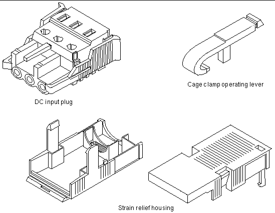
1. Identify the parts that you will use to assemble the DC input power cable (FIGURE 5-1).
The following DC connection parts are required to assemble one or more DC power input cables. These cables connect the -48V DC input source(s) to the power supply units.
2. Turn off power from the DC power source through the circuit breakers.

|
Caution - Do not proceed with these instructions until you have turned off the power from the DC power source through the circuit breakers. |
3. Get a DC input plug from the ship kit.
4. Locate the three wires coming from the DC power source that will be used in the connection to your unit:
|
Note - Depending on the DC power source, the -48V (negative terminal) might be marked with a minus (-) symbol, and the -48V Return (positive terminal) might be marked with a positive (+) symbol. |
5. Strip 5/16 inches (8 mm) of insulation from each of the wires coming from the DC power source.
Do not strip more than 5/16 inches (8 mm) from each wire. Doing so leaves uninsulated wire exposed from the DC connector after the assembly is complete.

6. Open the cage clamp for this section of the DC input plug by taking one of the following actions:
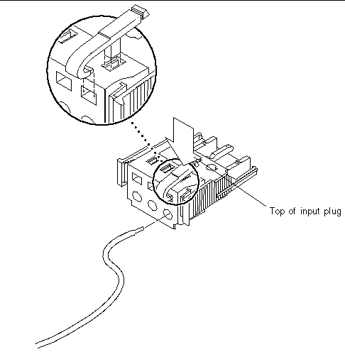
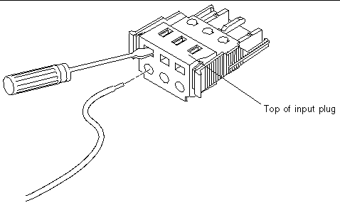
7. Feed the exposed section of the appropriate wire into the rectangular plug hole in the DC input plug.
FIGURE 5-5 shows which wires should be inserted into each hole in the DC input plug.

8. Repeat Step 6 and Step 7 for the other two wires to complete the assembly of the DC input power cable.
9. Repeat Step 4 through Step 8 to create as many DC input power cables as you need for your unit.
You need one DC input power cable for each of the two power supplies.
If you need to remove a wire from the DC input plug, insert the cage clamp operating lever or a small screwdriver into the slot directly above the wire and press down (FIGURE 5-3 and FIGURE 5-4). Pull the wire from the DC input plug.
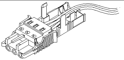
1. Insert the bottom portion of the strain relief housing into the notch on the DC input plug until it snaps into place.
Ensure that the strain relief housing snaps into place on the DC input plug. You cannot complete the assembly correctly if the strain relief housing is not snapped into place.
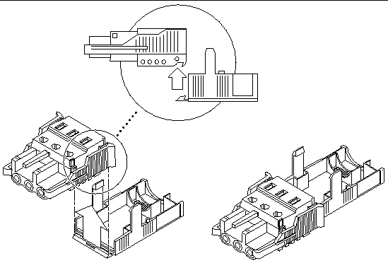
2. Route the three wires coming from the DC power source through the opening at the end of the bottom portion of the strain relief housing (FIGURE 5-7).
3. Insert a tie wrap into the bottom portion of the strain relief housing.
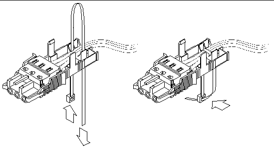
4. Loop the tie wrap over the wires and back out of the strain relief housing, and tightening the tie wrap to secure the wires to the strain relief housing (FIGURE 5-8).
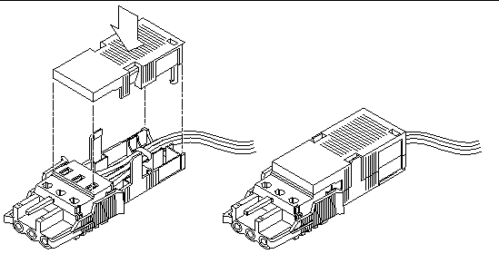
5. Lower the top portion of the strain relief housing so that the three prongs on the top portion insert into the openings in the DC input plug.
Push the top and bottom portions of the strain relief housing together until they snap into place.

|
Caution - An energy hazard is present when energized units are not properly earthed. |
1. Locate the DC connectors at the rear of the server.
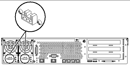
2. Connect the DC input power cables to the DC connectors.
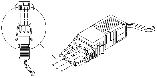
3. Turn on the circuit breakers to provide power to the servers.
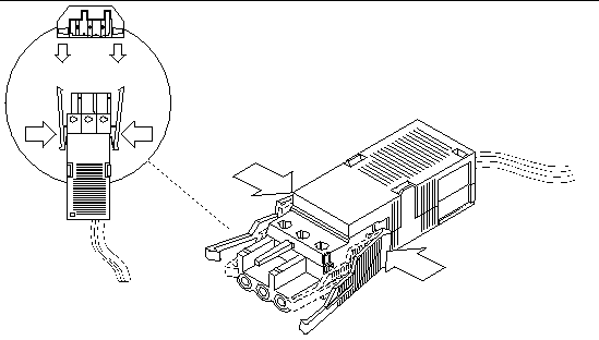
If you want to disconnect the DC input power cable from the DC connector at some point in the future, turn the circuit breakers off, then squeeze the two tabs on the sides of the DC input power cable and gently disconnect the DC input power cable from the DC power supply.

|
Caution - Do not attempt to disconnect the DC input power cable from the DC connector until you have turned off the power from the DC power source through the circuit breakers. |
|
Note - This section describes how to connect AC power cords to an AC-powered Netra 240 server. For DC-powered server instructions, see Assembling and Connecting the DC Input Power Cable. |
The two AC power supply units in the Netra 240 server allow for 1 + 1 power redundancy. If one power supply unit fails, then the system will continue to operate using the remaining power supply unit. Additionally, to ensure true AC line input redundancy for the server, you should connect each AC power cable to a different AC power source. You can also connect an uninterruptible power supply (UPS) between each AC power source and the server to increase the availability of the server.
1. Get the supplied AC power cords from the server's shipment kit.
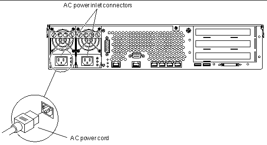
2. Connect one end of each AC power cord into the AC power inlet connectors located at the rear of the server.
See FIGURE 5-13 for the location of the AC power inlet connectors.
3. Connect the other ends of the power cords into AC wall outlets.
Connect each AC power cord to a different AC power source if you want AC line input power redundancy.
Copyright © 2004, Sun Microsystems, Inc. All rights reserved.