| Cluster Platform 15K/9960 System Site Planning Guide |
| Cluster Platform 15K/9960 System Site Planning Guide |
| C H A P T E R 2 |
|
Physical Specifications |
This chapter contains the physical specifications for the Cluster Platform 15K/9960 system.
The Cluster Platform 15K/9960 system consists of a two-node Sun Fire 15K domain cluster (each cluster domain is part of a separate Sun Fire 15K server) that has access to one Sun StorEdge 9960 shared storage system. The Cluster Platform 15K/9960 system includes the following components:
FIGURE 2-1 shows the cabinet configuration for the Cluster Platform 15K/9960 system.
FIGURE 2-1 Cluster Platform 15K/9960 System Cabinet Configuration
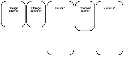
TABLE 2-1 lists the physical specifications for the Cluster Platform 15K/9960 system.
For detailed physical specifications of the expansion cabinet, refer to the Sun StorEdge Expansion Cabinet Installation and Service Manual. For detailed physical specifications of the Sun Fire 15K server, refer to the Sun Fire 15K Site Planning Guide. For detailed physical specifications of the Sun StorEdge 9960 storage system, refer to the Hitachi Freedom Storage Lighting 9900 User and Reference Guide.
A raised floor system provides a convenient way to duct cooling air and to route power and communication cabling. Sun strongly suggests that the system be installed on a raised floor to ensure that optimal cooling is available to the system. The computer room floor must be able to support the weight of the system cabinets.
Place perforated floor panels or floor grilles near or directly under the base of the system. Suggested locations for perforated floor panels or floor grilles are shown in Computer Room Layout. Use the floor layout diagram of the proposed location for the system to determine the exact area required for your system. Ensure the cabinets are positioned so that all casters and leveling feet are on solid raised-floor tiles.
Sun suggests a minimum raised floor height of 24-36 in. (61.0-91.5 cm).
If you are not installing your system on a raised floor, ensure the cooling requirements specified in TABLE 3-1 can be met. Use cable covers to protect personnel from injury and protect cables from damage.
|
Note - If the cooling to the system is inadequate, automatic system shutdown can result. |
For best performance, locate the system cabinets over perforated floor tiles as indicated in Computer Room Layout.
If your existing loading dock meets height or ramp requirements for a standard freight carrier truck, you can use a standard 60-inch pallet jack (at narrow end of pallet) to unload the system cabinets. If not, use a standard forklift (at wide side of pallet) or other means to unload the system, or request the system to be shipped in a truck with a lift gate. A standard forklift has a maximum outside tine dimension of 27 in. (68.6 cm) and a minimum inside tine dimension of 15 in. (38.1 cm).
Sun suggests that you leave each system component in its shipping crate until it reaches its unpacking destination. If the system component does not fit through the planned access route, it can be partially disassembled after the unit has been removed from the crate.
The entire access route to your computer room should be free of raised patterns that can cause vibration. In addition, the strength of the perforated tiles should be verified. It is common to see damaged floor tiles in delivery paths because of the repeated rolling loads. It is suggested that the entire raised-floor delivery path be protected with material such as heavy particle board or another material of similar strength.
|
Note - Any path in the access route must not have an incline more than 10 degrees. |
| Cluster Platform 15K/9960 System Site Planning Guide | 816-3537-10 |
Copyright © 2002, Sun Microsystems, Inc. All rights reserved.
