| Cluster Platform 15K/9960 System Site Planning Guide |
| Cluster Platform 15K/9960 System Site Planning Guide |
| C H A P T E R 3 |
|
Environmental Requirements |
The design of your environmental control system (such as computer room air-conditioning units) must ensure that intake air to the system meets the requirements specified in this chapter. Air enters the individual cabinets through the access panels and through air intakes that are located underneath the cabinets. The heated air is exhausted out of the top of the cabinets. Overheating can occur if warm air is directed underneath the cabinets or toward the access panels. TABLE 3-1 provides the environmental requirements for the Cluster Platform 15K/9960 system.
If the system components are significantly colder [40 °F (4 °C) or colder] than the environment in which you will install them, leave the system components in their shipping crates (at its final destination) for 24 hours to prevent thermal shock and condensation.
The suggested ambient temperature range of 70 degrees F to 74 degrees F (21 degrees C to 23 degrees C) is optimal for reliability and operator comfort levels. Most computer equipment can operate within a wide temperature range, but a level near 72 degrees F (22 degrees C) is desirable because it is easier to maintain safe associated relative humidity levels at this temperature. Operating in this temperature range provides a safety buffer just in case the environmental support systems go down for a period of time. Though individual standards vary slightly, 70 degrees F to 74 degrees F (21 degrees C to 23 degrees C) should be used as an optimal temperature choice.
The suggested ambient relative humidity levels between 45% and 50% are the most suitable for safe data processing operations. Under certain circumstances, most processing equipment can operate within a fairly wide environmental range (20% to 80%), but the optimal goal should be between 45% to 50% for several reasons:
Electrostatic discharge (ESD) is easily generated and less easily dissipated in areas where the relative humidity is below 35%, and becomes critical when levels drop below 30%. The 5% relative humidity range may seem unreasonably tight when compared to the guidelines used in typical office environments or other loosely controlled areas, but it is not so difficult to maintain in a data center because of the high efficiency vapor barrier and low rate of air changes normally present.
TABLE 3-2 contains the power and air conditioning information for the Cluster Platform 15K/9960 system.
The dynamics of the Cluster Platform 15K/9960 system power dissipation depends on application and configuration.
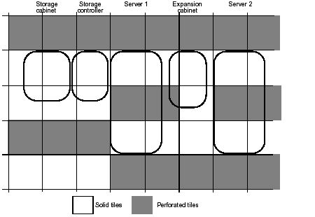
The location of the Cluster Platform 15K/9960 system on perforated floor tiles, and the number of tiles available to provide cooling air in a typical computer room raised floor environment, is critical to the overall cooling performance.
Each tile needs to be capable of delivering 600 cubic feet per minute (cfm) cooling air at 0.07 inches of water. Review the floor plan layout in FIGURE 3-1 for planning your solid and perforated tile floor configuration.
FIGURE 3-1 Solid and Perforated Tile Floor Plan
|
Note - Casters and leveling feet, located at the corners of each cabinet, are to be positioned only on solid floor tiles. |
| Cluster Platform 15K/9960 System Site Planning Guide | 816-3537-10 |
Copyright © 2002, Sun Microsystems, Inc. All rights reserved.