| C H A P T E R 1 |
|
Cluster Platform 280/3 Introduction |
This chapter describes the following information:
The Cluster Platform 280/3 system is a self-sustained platform, integrated through the Sun Cluster technology, with shared, mirrored Fibre-Channel Arbitrated Loop (FC-AL) storage to support highly available applications. You can use this two-node cluster system to implement a highly available file server, web server, mail server, or an Oracle® database server. Sun Cluster 3.0 provides global file systems, global devices, and scalable services. These features allow independent cluster nodes, running independent Solaris operating environment instances, to run distributed applications while providing client access through a single IP address.
|
Note - This cluster platform only provides a basic cluster environment. You must install and configure your data services after you have customized and configured the system. |
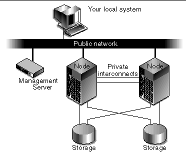
FIGURE 1-1 is a basic block diagram of the system, which includes a two-node cluster with shared, mirrored storage, a terminal concentrator, and a management server. An Ethernet hub provides connection between the cluster nodes, management server, and Sun StorEdge T3 arrays. The interfaces on both nodes are cabled to provide multiple cluster interconnects between nodes.
The management server is the repository for the operating environment, software, and patches. The management server provides access to the cluster console and functions as a JumpStart /Flash server (installation server) for the cluster nodes. For advanced system monitoring, the management server includes Sun Management Center software to monitor the cluster nodes.
The Cluster Platform does not have a monitor. You access the Cluster Platform using a system on the network that you provide (shown as your local system in FIGURE 1-1). The local system is simply used as a remote display to the management server. You do not need to dedicate any particular system as the local system. It can be any system that is convenient at the time.

Once the Cluster Platform 280/3 system configuration is complete, the following software components are installed:
 Management Center 3.0 Update 2 agent software
|
Note - To see the collection of patches that were installed on each cluster node, look in the /jumpstart/Patches/8_recommended directory of the management server. |
|
Note - Recovery disks are included with the Cluster Platform 280/3 system. The two disks included are the Cluster Platform 280/3 Mini Root CD and Cluster Platform 280/3 Recovery DVD. See To Use the Cluster Recovery Utility for recovery details. |
Your factory-integrated Cluster Platform 280/3 system includes the following hardware components:
 expansion cabinet which includes two power sequencers, one front door option, one rear door, and one fan assembly
 T1 AC200 server configured with one 500 MHz UltraSPARC
 IIe CPU, 1-Gbyte of memory, two internal mirrored 18-Gbyte boot disks, and a DVD-ROM drive
 280R servers, with two 750-MHz or 900-MHz UltraSPARC III CPUs, 2-Gbytes of memory, two mirrored 36-Gbyte boot disks, and a DVD-ROM drive
 T3 arrays, each with 1-Gbyte controller board cache and nine 36-Gbyte disks or 72.4-Gbyte disk drives.
 PCI cards per node installed in PCI1 and PCI2 slots; two FC-AL PCI host adapter cards per node installed in PCI3 and PCI4 slots
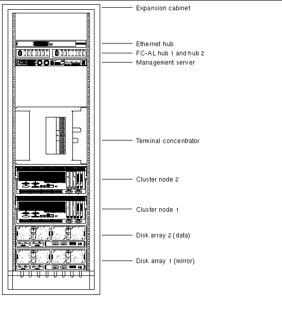
FIGURE 1-2 shows how the Cluster Platform 280/3 is arranged in the expansion cabinet. The hardware components are placed in the dual-power sequenced 72-inch expansion cabinets.
System components are cabled in the expansion cabinet to provide power and connections between the hardware components.
|
Note - The expansion cabinet arrangement complies with weight distribution, cooling, electromagnetic interference (EMI), and power requirements. |

The Cluster Platform 280/3 provides maximum connectivity in your enterprise network using the following network implementations:
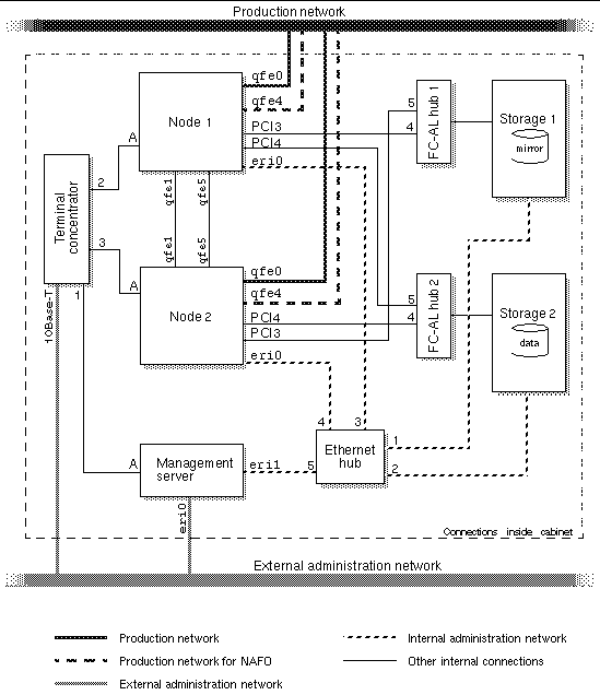
The Cluster Platform 280/3 system is shipped with the servers, hubs, and each of the arrays already connected in the cabinet. You do not need to cable the internal system components. The next chapter describes how to connect the Cluster Platform to your enterprise network.
For factory configured cable connections, see Appendix B.

The Cluster Platform 280/3 hardware must have two dedicated AC breakers. The cabinet should not share these breakers with other, unrelated equipment. The system requires two L30-R receptacles for the cabinet, split between two isolated circuits. For international installations, the system requires two Blue 32AIEC309 (international) receptacles.
If the cabinet is installed on a raised floor, cool conditioned air should be directed to the bottom of the expansion cabinet through perforated panels.
The 72-inch cabinet in the Cluster Platform 280/3 consumes power and dissipates heat as shown in TABLE 1-1.
Copyright © 2002, Sun Microsystems, Inc. All rights reserved.