| Cluster Platform 4500/3 User's Guide |
| Cluster Platform 4500/3 User's Guide |
| C H A P T E R 2 |
|
The Cluster Platform 4500/3 System |
The Cluster Platform 4500/3 system provides self-sustained platforms, integrated through the Sun Cluster technology, to support highly available applications. This two-node cluster system with shared, mirrored FC-AL storage can be used to implement a highly available file server, web server, mail server, or Oracle® database server.
Sun Cluster 3.0 provides global file systems, global devices, and scalable services. These features allow independent cluster nodes, running independent Solaris operating environment instances, to run distributed applications while providing client access through a single IP address.
|
Note - This Cluster platform only provides a basic cluster environment. Data services must be installed and configured by the customer. |
Your system includes a two-node cluster with shared, mirrored storage, a terminal concentrator, and a management server. The Sun StorEdge T3 arrays are connected to two FC-AL hubs. An Ethernet hub provides connection to the management server and Sun StorEdge T3 arrays. These components are cabled to provide redundant cluster interconnect between nodes, and to provide access to shared storage and production networks.
For more information on the T3 arrays, refer to Related Documentation.
The management server is the repository for software and patches that are loaded on the system. The management server provides access to the cluster console, and it functions as a JumpStart server (installation server) for the cluster nodes.
|
Note - The management server has sufficient CPU power and memory to implement a Sun |
To integrate your Cluster Platform 4500/3 into a production environment, you must:
1. Provide a name, IP address, and root password for the management server.
2. Provide a name and IP address for the terminal concentrator.
3. Provide a name for the cluster environment and a default router (gateway).
4. Provide names and IP addresses for individual cluster nodes.
5. Provide names and IP addresses for the Sun StorEdge T3 arrays.
6. Configure shared disk storage under Solstice DiskSuite or VERITAS volume manager. Configuration includes the creation of disksets (or disk groups), disk volumes, and file systems.
7. Select a quorum device from the shared disk storage.
8. Install and configure the required highly available applications.
9. Install and configure data services to support the highly available applications.
10. Configure network adapter failover (NAFO) for automatic failover.
|
Note - This document does not provide information to support items 6 through 9. For specific implementation details, refer to the Sun Cluster 3.0 documentation. |
The Ethernet address for each cluster node is located on the Customer Information, System Record sheet. Use the serial number on the information sheet and on the back of each node to correctly identify the Ethernet address. (See See Cluster Platform Rack Placement for the placement of each cluster node.)
FIGURE 2-1 shows the location of the Ethernet address for the disk array.
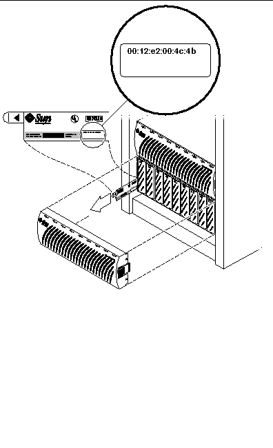
TABLE 2-1 provides a worksheet to assist with networking information. You will be referred back to the information you place in this table when you customize the cluster configuration.
The Cluster Platform 4500/3 software packages include the following:
FIGURE 2-3 shows cluster node interface hme1 providing network automatic failover (NAFO) for hme0 (production network). Interfaces hme2 and hme3 are available to expand application network services. Interfaces qfe0 and qfe4 are used for the cluster interconnect.
|
Note - See Ethernet IP Address Worksheet to specify the appropriate information for your network environment. |
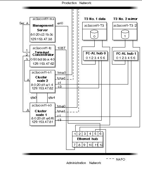
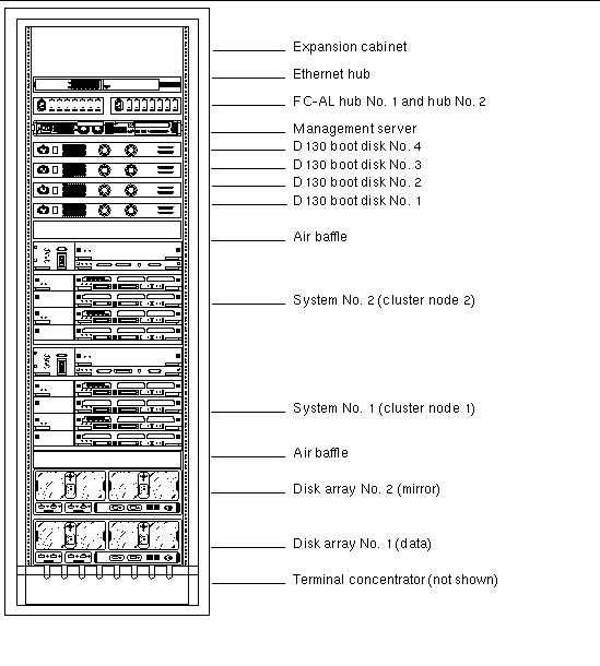
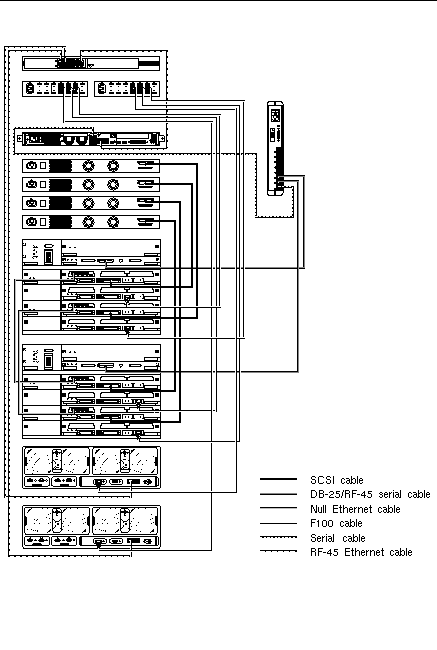
FIGURE 2-4 shows how the Cluster Platform 4500/3 is arranged in the expansion cabinet. FIGURE 2-2 lists the rack components and the quantities required.
|
Note - The rack arrangement complies with weight distribution, cooling, EMI, and power requirements. |
The Cluster Platform 4500/3 hardware should have two dedicated AC breaker panels. The cabinet should not share these breaker panels with other, unrelated equipment. The system requires two L30-R receptacles for the cabinet, split between two isolated circuits. For international installations, the system requires two Blue 32AIEC309 (international) receptacles.
If the cabinet is installed on a raised floor, cool conditioned air should be directed to the bottom of each rack through perforated panels.
The 72-inch cabinet in the Cluster Platform 4500/3 consumes power and dissipates heat, as shown in TABLE 2-3.
The Cluster Platform 4500/3 is shipped with the servers, hubs, and each of the arrays already connected in the cabinet. You should not need to cable the system. Refer to FIGURE 2-4 for servicing the cables.
This section describes how the Cluster Platform 4500/3 components are cabled when shipped from the factory. The integrated platform provides FC-AL cables connected to the on-board GBICs on the I/O board. Serial cables connect the Ethernet hub to the management server and 10BASE-T ports on the disk arrays.
For specific cabling connections, refer to Appendix C.

|
Caution - Partner pairs are not supported at this time. Do not connect the
|
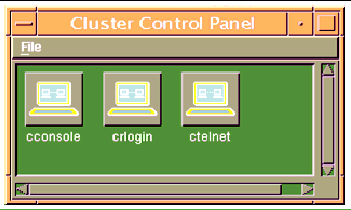
2. In the Cluster Control Panel window, double-click the Cluster Console (console mode) icon to display a Cluster Console window for each cluster node (see FIGURE 2-7).
|
Note - Before you use an editor in a Cluster Console window, verify that the TERM shell environment value is set and exported to a value of vt220. FIGURE 2-8 shows the terminal emulation in the Cluster Console window. |
To issue a Stop-A command to the cluster nodes and to access the OpenBoot PROM (OBP) prompt, position the cursor in the Cluster Console window, and enter the <ctrl>] character sequence. This character forces access to the telnet prompt. Enter the Stop-A command, as follows:
telnet> send brk ok> |
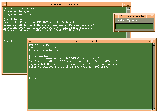
3. To enter text into both node windows simultaneously, click the cursor in the Cluster Console window and enter the text.
The text does not display in the Cluster Console window, and will display in both node windows. For example, the /etc/hosts file can be edited on both cluster nodes simultaneously. This ensures that both nodes maintain identical file modifications.
|
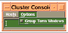
Note - The console windows for both cluster nodes are grouped (the three windows move in unison--FIGURE 2-7). To ungroup the Cluster Console window from the cluster node console windows, select Options from the Hosts menu (FIGURE 2-8) and deselect the Group Term Windows checkbox. |
1. Use the ccp(1M) Cluster Console window to enter the following command into both nodes simultaneously:
{0} ok setenv auto-boot? true {0} ok boot net - install |
|
boot net - You must use spaces between the dash (-) character in the
|
The Solaris operating environment, Solstice DiskSuite, and Sun Cluster 3.0 are automatically installed. All patches are applied and system files are configured to produce a basic cluster environment.
See Appendix B for sample output of the automatic installation of the first cluster node.
|
Note - Ignore any error messages received during the initial cluster installation. Do not attempt to reconfigure the nodes. |
2. Log into each cluster node as a superuser (password is abc) and change the default password to a secure password choice:
# passwd passwd: Changing password for root New password: secure-password-choice Re-enter new password: secure-password-choice |
3. Configure the Sun StorEdge T3 array shared disk storage, using the Solstice DiskSuite software.
Solstice DiskSuite configuration involves creating disksets, metadevices, and file systems. (Refer to the included Solstice DiskSuite documentation.)
4. Select a quorum device to satisfy failure fencing requirements for the cluster. (Refer to the included Sun Cluster 3.0 documentation.)
5. Install and configure the highly available application for the cluster environment. (Refer to the Sun Cluster 3.0 documentation.)
6. Establish resource groups, logical hosts, and data services to enable the required application under the Sun Cluster 3.0 infrastructure. (Refer to the Sun Cluster 3.0 documentation.)
Your customized Cluster Platform 4500/3 is completed.
The recovery CDs enable you to replace the factory-installed Cluster Platform
4500/3 software environment on the management server in the event of a system disk failure.

|
Caution - Initiate a recovery only at the direction of technical support. |
These CDs are intended only for recovering from a disaster. They are not needed for initial installation and configuration of the Cluster Platform 4500/3 management server.
Before you attempt to restore the management software environment, you must know your system configuration information and the state of your system backups. See TABLE 2-1 on "Invalid Cross-Reference Format" for information on your customized configuration.
Your system configuration information must include the following:
1. Access the management server console through the terminal concentrator:
# telnet sc3sconf1-tc Trying 148.212.87.62... Connected to sc3sconf1-tc. Escape character is '^]' <CR> Rotaries Defined: cli Enter Annex port name or number: 1 |
2. To issue a Stop-A command to the cluster nodes and to access the OpenBoot PROM (OBP) prompt, position the cursor in the Cluster Console window and enter the <ctrl>] character sequence.
3. This character forces access to the telnet prompt. Enter the Stop-A command, as follows:
telnet> send brk |
4. Boot the system from the CD-ROM:
ok boot cdrom |
The system boots from the CD-ROM and prompts you for the mini-root location
(a minimized version of the Solaris operating environment). This procedure takes approximately 15 minutes.
5. Select a CD-ROM drive from the menu.
Once the Cluster Platform 4500/3 recovery utility has placed a copy of the Solaris operating environment onto a suitable disk slice, the system reboots. You are prompted to specify the CD-ROM drive. Completing this process takes approximately 15 minutes.
6. Install the Solaris operating environment software.
You are prompted to remove CD0 and mount CD1 on the CD-ROM drive. After
CD1 is mounted, press the Return key. The Solaris operating environment files are copied from CD1 onto the management server boot disk. This process takes approximately 20 minutes.
7. Install the second data CD.
When all files are copied from the first data CD, you are prompted to remove CD 1 and mount CD 2 on the CD-ROM drive. After CD 2 is mounted, press the Return key. The software and patch files are copied from CD 2 onto the management server boot disk. When all files are copied from both CDs, the system automatically shuts down. You must reboot the system. This process takes approximately 20 minutes.
Once the management server recovery software is loaded, you must configure the system to match your environment. Refer to Customizing the Cluster Platform 4500/3 to customize your cluster environment. If the recovery process involves the replacement of cluster nodes, refer to Ethernet IP Address Worksheet to verify that the first cluster node's FC-AL is properly set up.
| Cluster Platform 4500/3 User's Guide | 816-0445-11 |
Copyright © 2002, Sun Microsystems, Inc. All rights reserved.
