| Netra 20 Installation and User's Guide
|
   
|
This chapter provides information about the external I/O connectors.
The chapter contains the following sections:
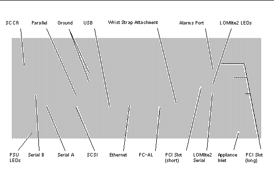
FIGURE 4-1 shows the locations of the Netra 20 system rear panel connectors.
FIGURE 4-1 Rear Panel Connectors (AC System Shown)

Parallel Connector
FIGURE 4-2 DB-25 Parallel Connector

TABLE 4-1 Parallel Connector Pinout
|
Pin
|
Signal Name
|
I/O
|
Service
|
|
1
|
DATA_STROBE_L
|
|
Data Strobe (active LOW)
|
|
2
|
DAT(0)
|
|
Data Bit 0
|
|
3
|
DAT(1)
|
|
Data Bit 1
|
|
4
|
DAT(2)
|
|
Data Bit 2
|
|
5
|
DAT(3)
|
|
Data Bit 3
|
|
6
|
DAT(4)
|
|
Data Bit 4
|
|
7
|
DAT(5)
|
|
Data Bit 5
|
|
8
|
DAT(6)
|
|
Data Bit 6
|
|
9
|
DAT(7)
|
|
Data Bit 7
|
|
10
|
ACK_L
|
|
Acknowledge (active LOW)
|
|
11
|
BSY
|
|
Busy (active HIGH)
|
|
12
|
PERROR
|
|
Paper End (active HIGH)
|
|
13
|
SELECT_L
|
|
Select (active LOW)
|
|
14
|
AFXN_L
|
|
Auto Line Feed (active LOW)
|
|
15
|
ERROR_L
|
|
Error (active LOW)
|
|
16
|
RESET_L
|
|
Initialize Printer (prime active LOW)
|
|
17
|
IN_L
|
|
Select Input (active LOW)
|
|
18
|
GND
|
|
Ground
|
|
19
|
GND
|
|
Ground
|
|
20
|
GND
|
|
Ground
|
|
21
|
GND
|
|
Ground
|
|
22
|
GND
|
|
Ground
|
|
23
|
GND
|
|
Ground
|
|
24
|
GND
|
|
Ground
|
|
25
|
GND
|
|
Ground
|
Serial Connectors
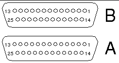
FIGURE 4-3 DB-25 Serial Connectors

TABLE 4-2 Serial Connector Pinout, RS423/RS232
|
Pin
|
Function
|
I/O
|
Signal Description
|
|
1
|
|
|
Not connected
|
|
2
|
TxD
|
O
|
Transmit Data
|
|
3
|
RxD
|
I
|
Receive Data
|
|
4
|
RTS
|
O
|
Ready To Send
|
|
5
|
CTS
|
I
|
Clear To Send
|
|
6
|
DSR
|
I
|
Data Set Ready
|
|
7
|
GND
|
|
Signal Ground
|
|
8
|
DCD
|
I
|
Data Carrier Detect
|
|
9-14
|
|
|
Not connected
|
|
15
|
TRxC
|
I
|
Transmit Clock
|
|
16
|
|
|
Not connected
|
|
17
|
RTxC
|
I
|
Receive Clock
|
|
18-19
|
|
|
Not connected
|
|
20
|
DTR
|
O
|
Data Terminal Ready
|
|
21-23
|
|
|
Not connected
|
|
24
|
TxC
|
O
|
Transmit Clock
|
|
25
|
|
|
Not connected
|
SCSI Connector
FIGURE 4-4 68-Pin SCSI Connector

TABLE 4-3 68-Pin SCSI Connector Pinout
|
Pin
|
Signal Name
|
Pin
|
Signal Name
|
|
1
|
GND
|
21
|
GND
|
|
2
|
GND
|
22
|
GND
|
|
3
|
GND
|
23
|
GND
|
|
4
|
GND
|
24
|
GND
|
|
5
|
GND
|
25
|
GND
|
|
6
|
GND
|
26
|
GND
|
|
7
|
GND
|
27
|
GND
|
|
8
|
GND
|
28
|
GND
|
|
9
|
GND
|
29
|
GND
|
|
10
|
GND
|
30
|
GND
|
|
11
|
GND
|
31
|
GND
|
|
12
|
GND
|
32
|
GND
|
|
13
|
GND
|
33
|
GND
|
|
14
|
GND
|
34
|
GND
|
|
15
|
GND
|
35
|
-DB<12>
|
|
16
|
GND
|
36
|
-DB<13>
|
|
17
|
TERMPWR
|
37
|
-DB<14>
|
|
18
|
TERMPWR
|
38
|
-DB<15>
|
|
19
|
Not connected
|
39
|
-PAR<1>
|
|
20
|
GND
|
40
|
-DB<0>
|
|
41
|
-DB<1>
|
55
|
-ATN
|
|
42
|
-DB<2>
|
56
|
GND
|
|
43
|
-DB<3>
|
57
|
-BSY
|
|
44
|
-DB<4>
|
58
|
-ACK
|
|
45
|
-DB<5>
|
59
|
-RST
|
|
46
|
-DB<6>
|
60
|
-MSG
|
|
47
|
-DB<7>
|
61
|
-SEL
|
|
48
|
-PAR<0>
|
62
|
-CD
|
|
49
|
GND
|
63
|
-REQ
|
|
50
|
TERM.DIS
|
64
|
-IO
|
|
51
|
TERMPWR
|
65
|
-DB<8>
|
|
52
|
TERMPWR
|
66
|
-DB<9>
|
|
53
|
Reserved
|
67
|
-DB<10>
|
|
54
|
GND
|
68
|
-DB<11>
|
|
Note - All signals shown in TABLE 4-3 are active low.
|
SCSI Implementation
- SCSI-3 Fast-20 (UltraSCSI) parallel interface external 16-bit single-ended bus
- 40 Mbps data transfer rate
- Support for 16 SCSI addresses:
- Target 0 to 6 and 8 to F for devices
- Target 7 reserved for SCSI host adapter on main logic board
- Support for up to three internal devices (including the host adapter) on an 8-bit, narrow single-ended bus:
- Fast-20 SCSI removable media device target 4
- Fast-20 SCSI removable media device target 6
- Fast-10 SCSI removable media device DAT target 5
- Fast-10 SCSI removable media device DVD-ROM target 6
- Support for external 8-bit and 16-bit SCSI devices via 68-pin SCSI connector mounted on an adapter board
SCSI Cabling and Configuration
The SCSI-3 Fast-20 (UltraSCSI) specification requires that the external SCSI bus length be limited to 3m (10 feet) for less than five devices (internal and external), and 1.5m (5 feet) for five to eight devices. When SCSI-3 and SCSI-2 devices are connected to the Netra 20 system SCSI bus, the system enables each device to operate at its respective data transfer rate. The last external SCSI device in a daisy-chain must be terminated internally (active termination) or with an external terminator according to Forced-Perfect Termination (FPT) technology.
SCSI Cabling Procedure
1. Count the number of SCSI devices on the system SCSI bus. Be sure to count the host adapter as a SCSI device.
2. Determine the total SCSI bus length.
TABLE 4-4 Determining SCSI Bus Length
|
SCSI Implementation
|
Bus Width
|
Data Transfer Rate, Mb/s
|
Number of Devices
|
SCSI Bus Length
|
|
SCSI-2, Fast
|
8 bits
|
10
|
1-8
|
6.0 m
|
|
SCSI-2, Fast/Wide
|
16 bits
|
20
|
1-8
|
6.0m
|
|
SCSI-3 Parallel Interface, Fast-20 Wide
(UltraSCSI) (WideUltra)
|
16 bits
|
40
|
1-4
|
3.0 m
|
|
SCSI-3 Parallel Interface, Fast-20 Wide
(UltraSCSI) (WideUltra)
|
16 bits
|
40
|
5-8
|
1.5 m
|
3. Verify the cable type used to connect external SCSI devices. You must use Fast-20 SCSI cable(s).
Ensure that the total SCSI cable length does not exceed the permissible total SCSI bus length.
SCSI-2 (UltraSCSI) External Devices
If you connect SCSI-2 (UltraSCSI, 40 Mb data transfer rate) external devices to a Netra 20 system, follow these cabling and configuration guidelines (as shown in FIGURE 4-5) to ensure proper device addressing and operation:
- If all external mass storage devices use 68-pin connectors, connect all non Sun devices to the Netra 20 system first and follow them with Sun devices. Sun devices use auto-termination.
- If external mass storage devices consist of 68-pin Sun devices and 50-pin devices, connect the Sun 68-pin devices to the Netra 20 system first and terminate the daisy chain with the 50-pin device and its terminator.
- The total SCSI bus length for all external SCSI devices is 6.0m (19.7ft), including the internal cabling.
FIGURE 4-5 Connecting External Mass Storage Devices

Ethernet Connector
FIGURE 4-6 RJ45 TPE Socket

TABLE 4-5 TPE Connector Pinout
|
Pin
|
Description
|
Pin
|
Description
|
|
1
|
Transmit Data +
|
5
|
Common Mode Termination
|
|
2
|
Transmit Data -
|
6
|
Receive Data -
|
|
3
|
Receive Data +
|
7
|
Common Mode Termination
|
|
4
|
Common Mode Termination
|
8
|
Common Mode Termination
|
TPE Cable-Type Connectivity
The following types of twisted-pair Ethernet cable can be connected to the
8-pin TPE connector:
- For 10BASE-T applications, shielded twisted-pair (STP) cable:
- Category 3 (STP-3, voice grade)
- Category 4 (STP-4)
- Category 5 (STP-5, data grade)
- For 100BASE-T applications, shielded twisted-pair category 5 (STP-5, data grade) cable.
TABLE 4-6 TPE STP-5 Cable Lengths
|
Cable Type
|
Application(s)
|
Max Length (Metric)
|
Max Length (Imperial)
|
|
Shielded twisted pair category 5 (STP-5, data grade)
|
10BASE-T
|
1000 m
|
3281 feet
|
|
Shielded twisted pair category 5 (STP-5, data grade)
|
100BASE-T
|
100 m
|
328 feet
|
FC-AL Connector
FIGURE 4-7 FC-AL Connector

TABLE 4-7 FC-AL Connector Pinout
|
Pin
|
Description
|
Pin
|
Description
|
|
1
|
Transmit Data TX_P
|
5
|
|
|
2
|
|
6
|
Receive Data TX_N
|
|
3
|
Transmit DataTX_N
|
7
|
|
|
4
|
|
8
|
Receive Data TX_P
|
FC-AL connector pinout.
USB Connectors
FIGURE 4-8 USB Connector

TABLE 4-8 USB Connector Pinout
|
Pin
|
Description
|
Pin
|
Description
|
|
1
|
VCC +5 VDC
|
3
|
Data +
|
|
2
|
Data -
|
4
|
Ground
|
Alarms Ports
The alarms service port connector (male DB-15) and LOM port connector (RJ45) are located on the alarms card. TABLE 4-9 list the pinouts for the alarms service port connector.
FIGURE 4-9 DB-15 (Male) Alarms Service Port Connector

TABLE 4-9 Alarms Service Port Connector Pinout
|
Pin
|
Signal Name
|
Pin
|
Signal Name
|
|
1
|
Not connected
|
9
|
ALARM1_NC
|
|
2
|
Not connected
|
10
|
ALARM1_COM
|
|
3
|
Not connected
|
11
|
ALARM2_NO
|
|
4
|
Not connected
|
12
|
ALARM2_NC
|
|
5
|
SYSTEM_NO
|
13
|
ALARM2_COM
|
|
6
|
SYSTEM_NC
|
14
|
Not connected
|
|
7
|
SYSTEM_COM
|
15
|
Not connected
|
|
8
|
ALARM1_NO
|
Shell
|
CHGND
|
The remote Lights Out Management serial port is located below the alarms port. The connector is a shielded RJ45 and TABLE 4-10 lists the connector pinout.
FIGURE 4-10 RJ45 Lights Out Management Serial Connector

TABLE 4-10 Lights Out Management Serial Connector Pinout
|
Pin
|
Signal Name
|
Pin
|
Signal Name
|
|
1
|
RTS
|
5
|
REF (0V)
|
|
2
|
DTR
|
6
|
RXD
|
|
3
|
TXD
|
7
|
DSR
|
|
4
|
REF (0V)
|
8
|
CTS
|
|
Shell
|
CHGND
|
System Configuration Card Reader
The slot for system configuration card reader (SCCR) smart card is located at the extreme left hand side of the rear panel (see FIGURE 4-1). For details of the SCCR refer to Chapter 9.


