| C H A P T E R 3 |
|
Installing the Electrical Supply |
This chapter provides information about the electrical supply installation and the operating characteristics of the AC and DC power supply units.
The chapter contains the following sections:
The maximum input current, power and thermal dissipation for the Netra 20 are as follows:
The AC server has an IEC 60320 appliance coupler for connection to mains power.
The AC power cord is the primary means of disconnection for the AC system.
The maximum inrush current is 25 Apeak upon start up or restart after power has been removed for 60 s or longer. Circuit breakers must not be tripped by an inrush current of 25 A lasting 200 ms.
The maximum normal input line current is less than 7.2 Arms at 100 VAC under standard test conditions.
The maximum input power of the system in power off or remote off state is less
than 30 VA.
The site requirements for the AC power source are as follows:
|
Note - Overcurrent devices must meet applicable national and local electrical safety codes and be approved for the intended application. |
The disconnect devices for servicing are defined as:
Ensure that these remain accessible after installation.

|
Caution - External filtering and/or surge suppression devices may be required on the power feeds where branch circuit electromagnetic characteristics are unknown. |
The AC outlet socket should be protected by a 15 A double-pole double-throw circuit breaker.
Two M5 studs and cupwasher nuts are supplied on the rear of the chassis for connection.
The safety earth path is established by the connection of the grounding conductor within the AC power cord to a reliably earthed socket outlet located near the equipment.
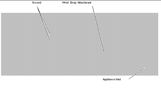

|
Caution - Do not open the top access cover until you have powered down the system and removed the power cable. |
The maximum continuous output power rating is 500 W for single or dual input supply. The maximum continuous rating per output is shown in TABLE 3-3.
The DC system has two 3-position Wago connectors per power supply. The mating connectors are specified in the section Power and Grounding Connections.
To isolate the system, break all connections by opening all external circuit breakers.
|
Voltage[1] |
|
|
Note - Overcurrent devices must meet applicable national and local electrical safety codes and be approved for the intended application. |
The disconnect devices for servicing are defined as:
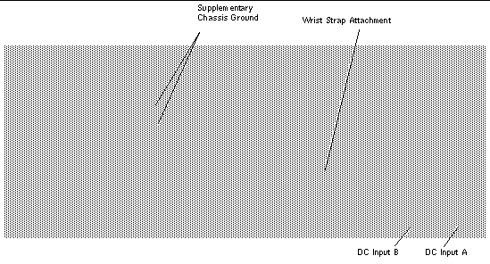

|
Caution - External filtering and/or surge suppression devices may be required on the power feeds where branch circuit electromagnetic characteristics are unknown. |
|
Note - It is good practice to connect the chassis grounding conductor before applying power to the system via the Wago connectors. |

|
Caution - Do not open the top access cover until you have powered down the system and removed the DC source from both input connectors. |
The maximum continuous output power rating is 500 W for single or dual input supply. The maximum continuous rating per output is shown in TABLE 3-5.
The following DC connection materials are provided in the DC input connector kit:



FIGURE 3-6 shows the power connector on the DC power supply on your system.
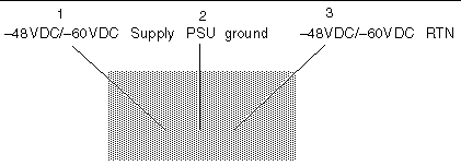
1. Turn off power to the DC power source by opening the circuit breakers.

|
Caution - Do not proceed with these instructions until you have turned off the power to the DC power source through the circuit breakers. |
2. Strip 8mm (0.31 inches) of insulation from each of the wires to be fitted to the connector.
Do not strip more than 8 mm (0.31 in.) from each wire. Doing so will leave uninsulated wire exposed from the DC input connector after the assembly is complete.

3. Using a DC connector from the kit, insert the tip of a cage clamp operating lever into the rectangular hole directly above the hole in the DC connector where you want to insert the first wire and press down on the cage clamp operating lever.
This opens the cage clamp for this section of the DC input connector.
You can also open the DC connector cage clamp by inserting a small slotted screwdriver into the rectangular hole directly above the hole in the DC connector where you want to insert the first wire and pressing down on the screwdriver.
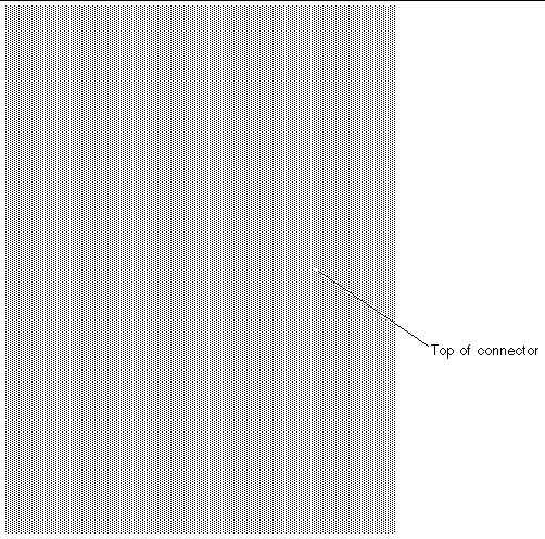
4. Feed the stripped end of each wire into the appropriate hole in the DC input connector.
FIGURE 3-9 shows which wires should be inserted into each hole in the connector.

5. Repeat Step 3 and Step 4 for the other two wires to complete the assembly of the DC input power cable.
6. If you are not using the optional strain relief housing, secure the wires together with a wire tie.
7. Repeat Step 2 through Step 6 to wire the other DC input power connector.
Note that you will require a separate DC power source for each DC input.
If you need to remove a wire from the DC input connector, insert the cage clamp operating lever or a small screwdriver into the slot directly above the wire to free the wire from the cage clamp, and press down (FIGURE 3-8).
1. Take the DC input connector and insert the bottom portion of the strain relief housing into the notch on the DC input connector until it snaps into place.
Make sure the strain relief housing snaps into place on the DC input connector; you will not be able to complete the assembly correctly if the strain relief housing is not snapped into place.

2. Route the three wires coming from the DC power source through the opening at the end of the bottom portion of the strain relief housing.

3. Insert the wire tie into the bottom portion of the strain relief housing.

4. Loop the wire tie over the wires and back out of the strain relief housing, then tighten the wire tie to secure the wires to the strain relief housing (FIGURE 3-12).
5. Lower the three prongs on the top portion of the strain relief housing into the openings in the DC input connector, then push the top portion and bottom portion of the strain relief housing together until they snap into place.

The DC input power cables for your system are now completely assembled. FIGURE 3-14 shows how the DC input power cable will connect to the DC inlet connector.
The system switch of the Netra 20 system functions as a standby device enabling and disabling the power module outputs. The system switch is a rocker, momentary switch.
The system does not contain any integral circuit breakers. To isolate the system from the mains power, you must remove the input power connector.
|
Note - The ON/STBY switch handles low voltage signals only; the high-power circuits do not pass through this switch. |
Prior to powering on, inspect the supply conductors for mechanical security.
1. Plug the system into the mains supply.
2. Momentarily set the front panel ON/STBY system switch to the ON position and hold it until the system starts to power up.
1. Insert both DC input connectors.
2. Close both DC circuit breakers.
3. Momentarily set the front panel ON/STBY system switch to the ON position and hold it until the system starts to power up.
Chapter 8 describes how to power off the system using software.

|
Caution - Before turning off system power, exit from the operating system. Failure to do so may result in data loss. |
1. Where necessary, notify the users that the system is going down.
2. Back up system files and data.
4. Momentarily set the front panel ON/STBY system switch to the STBY  position until the system powers down.
5. Verify that the Power LED is off.
6. Disconnect the AC power connector from the rear of the system.

|
Caution - Regardless of the position of the ON/STBY switch, where an AC power cord remains connected to the system, potentially dangerous voltages could be present within the power supply. |
1. Where necessary, notify the users that the system is going down.
2. Back up system files and data.
4. Momentarily set the front panel ON/STBY system switch to the STBY  position until the system powers down.
5. Verify that the Power LED is off.
6. Open both DC circuit breakers.
7. Detach both DC input connectors.
Copyright © 2003, Sun Microsystems, Inc. All rights reserved.