| C H A P T E R 1 |
|
Product Overview |
This chapter describes the Sun Fire B10n blade hardware and software and lists both its features and the requirements for using it.
This chapter contains the following sections:
Refer to the latest issue of the Sun Fire Blade Application Journal for further configuration and architectural overiew information. The Application Journal is available at: http://processors.sfbay/ns/spblades/
The Sun Fire B10n blade is a networking product that provides content load balancing for Sun's blade-based servers and other horizontally scaled Sun platforms. It is designed to work in the management framework of the Sun Fire B1600 blade system chassis. As part of the Sun Fire B1600 blade system chassis, the Sun Fire B10n blade connects to the Sun Fire B1600 blade system chassis midplane through two Gigabit Ethernet interfaces. The blade offers Layer 4 through Layer 7 load balancing. The server decision can be based on IP protocol, IP persistence, and TCP/UDP ports (Layer 4) or URLs, cookies, cookie persistence, and CGI scripts (Layer 7). Both these functions can operate up to the two Gigabit full-duplex line rate.
The Sun Fire B10n blade implements hardware assisted direct server to client response load balancing, which enables the switch capacity to be used for aggregate responses rather than individual link capacity to the blade. To enable this server to client direct data flow, you must install a software module (Server Module) on each server.
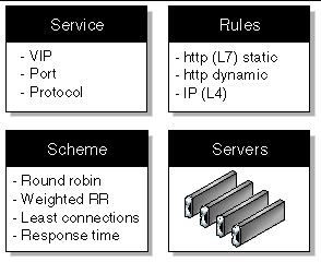
From a logical perspective, the following components make up a Sun Fire B10n blade:
The Sun Fire B10n blade provides optimized server to client response. To support this response and provide tight communications between the content load balancing blade and the B1600 blade servers a software module must be installed on each of these servers. This software module is referred to as the Server Module and is loaded using the Unix package add (pkgadd) process.
The content load balancing blade is based on specialized hardware including a general purpose microprocessor that runs a real time operating system. The code that runs on this processor is called the Application Software and can be updated using a TFTP process.
In addition to the general purpose processor there is a micro controller called the Blade Support Controller (BSC). The BSC is the primary interface to the Sun Fire B1600 Service Controllers (SC) and performs the Advanced Lights-out Management (ALOM) function for a given blade. These functions include powering on and off of the blades as well as monitoring functions. This is referred to as the BSC Firmware and can be updated using the "flashupdate" command which involves using TFTP.
The Sun Fire B10n software components:
Check the following web site to ensure you have the latest Sun Fire B10n software:
http://wwws.sun.com/software/download/network.html
The Sun Fire B10n blade has the capability to hold two versions of the Application Software and a diagnostic image. This allows a new image to be loaded without overwriting the active image. The blade must be rebooted to activate an image. See Choosing the Boot Image.
The B10n specialized hardware includes a rule based classification engine. The rules are entered through the command line interface and then compiled using a build process. See Creating an HTTP Load Balancing Rule.
Configuration of the load balancing blade can be achieved directly through the Command Line Interface (CLI) or by importing configuration files. The CLI interface is scriptable and access is through the B1600 chassis Service Controller (SC) interface. Connection to the SC can be direct RS232 or Telnet of the 10/100 ethernet port. (See Chapter 4.)
Before using the Sun Fire B10n blade, ensure your system meets the hardware and software requirements listed in TABLE 1-1. If you need a server module for a later operating system release check the Sun Download Center at:
http://wwws.sun.com/software/download/network.html
|
|
|
The supported operating systems for the Sun Fire B10n blade are listed in TABLE 1-2.
Zip files are available at the Sun Download Center at the following URL:
http://wwws.sun.com/software/download/network.html
Enter B10n and select Search the Download Center. Select Sun Fire B10n Content Load Balancing. Zip files listed in TABLE 1-3 are available.
|
SunFire_B10n-version#-SolarisModule.zip SunFire_B10n-version#-LinuxModule.zip
|
|
The Sun Fire B10n blade uses the following protocols for its services or management functions:
The load balancer monitors the servers using the CLB heartbeat message and the server module in the heartbeat response sets of the number of current open connections. This value is used by the load balancer to make the load balancing decision.
The underlying load balancing scheme in this mechanism is weighted round robin. The active connection count of the servers is used to compute the weight of each server dynamically and balance load based on the computed weight.
The number of connections active on a server indicates the amount of load a server is handling. Using this indication to dynamically adjust the weight of the servers maintains a steady load and minimizes the chances a server getting overloaded and others underloaded.
Every load balancing group could have a disparate set of servers with single and multiple CPU systems and various CPU frequencies in them, and could handle different connection rates. Doing a pure least connection algorithm in this environment could cause the less powerful (slower and fewer CPUs) servers to be overloaded while the more powerful system could be underloaded. To solve this problem each server is assigned a weighting factor. This factor in the CLI would be the same parameter as the weight specified in weighted round robin. The more powerful systems are given a higher weight and the slower systems are given a lower weight. When the relative connection count of the servers is computed, this weight is applied to the connections and then the new weight for the servers is computed.
The dependencies of the weighted least connections feature are as follows:
Since the connection count is obtained from the server monitoring information in the heartbeat message, this scheme depends on the server monitoring frequency being fairly high. If the frequency is too low the active connections sample might not represent the current state of the system.
The rate at which the weight is updated also affects the behavior. If the frequency is greater than the server monitoring frequency, then the updates will use the old connection count and is not of much use. If the frequency is too low, the weight might not reflect the current state of the system. This is not user configurable and is set at either compile time or read using property files.
Unlike weighted round robin or round robin, there is not a specific indication of when the servers are correctly load balanced. This is because the weights are dynamically computed.
One possible way to know if the servers are correctly load balanced is to have some servers common in two different load balancing groups and have the group's load balancing scheme set to weighted least connection and observe if an average of all the server loads are approximately the same. If different types of servers are used, the weight should be applied to the connection count which is dividing the connection count of a server by its defined weight. These counts should be approximately equal.
Protocol specific requests are sent to each server in the service and when the response is received, it is verified for correctness. The overall response time is also measured for use with response time based load balancing.
For HTTP, first a TCP connection is established and then a GET request for a specified URL is sent. When the response is received, the response code is checked for 200 (OK). The overall response time is also measured for use with response time based load balancing.
If the response code is not 200, the connection times out and the application is marked as down, and connections are not load balanced to that server.
The Sun Fire B10n blade is a component within a larger system ultimately delivering highly available network services to a client population over an IP-based network. This section describes the role of such a highly integrated content load balancer within the larger system.
The minimal set of components comprising the system encompasses:
Additionally, the system may have:
In general terms, the intra-shelf network topology formed by connecting the Sun Fire B1600 system components is either a single or a dual redundant Layer 2 topology with blades "one-arm" connected to each of the switch fabrics. The switch fabric is VLAN partitionable for strict traffic isolation. SSC switches and uplinks can be used for a simple inter-shelf network, or connected to external distribution switches for larger configurations.

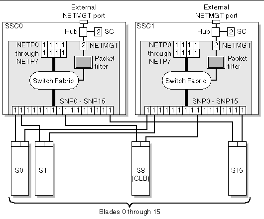
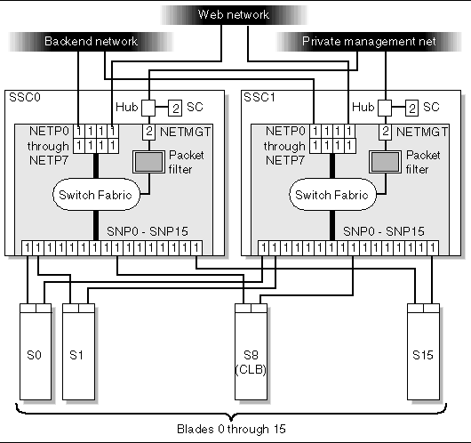
FIGURE 1-1 shows the intra-shelf network, where a Sun Fire B10n blade (shown in slot S8) can reside in any slot (S0 through S15) and connect to both SSC0 and SSC1 switch fabrics. The uplinks are labeled NETP0 through NETP7.
The numerals associated with each port (either 1 or 2), represent the VLAN numbers programmed into the system by default. The numbers indicate that there is one data VLAN (1), and one management VLAN (2). Further VLAN partitioning might be desirable as shown in FIGURE 1-2. The actual VLAN-ID assignment can be coordinated with the VLANs used in the external switches, or its scope can be limited to the internal switches, by keeping the uplinks as untagged VLANs.

The role of the content load balancer is to present a set of highly available network services. These services can be transported over http, TCP, or UDP, and are addressable through one or more Virtual IP addresses (VIPs), that the content load balancer is responsible for:
VIPs are the routable IP addresses that clients obtain for the service though DNS lookups. A VIP address is owned by one content load balancer at a given time. VIPs are preserved through the content load balancer all the way to servers. Requests are directed to servers by rewriting their MAC addresses and their VLAN tags.
A service is identified by a 3-tuple comprising of the VIP, the Layer 4 protocol value (TCP or UDP), and TCP/UDP destination port. A multi-homed service can be associated with more than one 3-tuple. For example, two different VIPs can point to the same service. One of the initial steps in setting up the load balancer is to configure a service through the command line interface. Configurations can be input through the console interface by manual command line entry, scripted command sets or importing config files.
Load balancing or the server forwarding decision for a particular service is controlled by one or more rules. There are three basic types of rules, IP rules (layer 4), static HTTP and dynamic HTTP. An IP rule consists of source IP and source port, both have associated masks which enable subnets or port groups to be defined. Static HTTP (Layer 7) provides direct URL matching where as dynamic HTTP provides wild carding of various parameters. Rule matching is based on a priority match where priority is determined by rule type or assigned priority. If IP rule priority is Low, the order is HTTP static, HTTP dynamic, and IP rule. If IP rule priority is set to High, the order is IP rule, HTTP static and HTTP dynamic. The number of bits configured determines order within a rule type.
The next parameter in the server decision is the type of load balancing scheme. The schemes currently supported are round robin, weighted round robin, least connections, response time and static.
A service, load balancing scheme and servers are associated by creating a load balancing group using the lb-group command.

For more details on command syntax for creating services, rules, and load balancing groups see Appendix D. Additionally, for an example, see Appendix B.
To match the ample switching capacity of the SSC units in the Sun Fire B1600 blade platform the content load balancer solution is designed to direct server responses toward clients without passing through the content load balancer. This enables the outbound capacity of the system to scale in proportion to the number of servers deployed, and to exploit the natural web traffic asymmetry where most of the traffic is server outbound.
To combine the uncompromised Layer 7 service performance with the direct server response, the content load balancing blade relies on a software module in each server. This server module contributes to the solution's high degree of integration by providing other key attributes, for example, path failover functionality.
The Sun Fire B1600 blade platform switches are separate networks, leaving the system designer the option to connect them externally and create a symmetrically configured redundant system where every blade is dual-homed, or to leave the switches segregated for a system where full redundancy is either not necessary (or achieved elsewhere in the system hierarchy), and blades are single-homed to separate networks. You can also create intermediate configurations where critical blades (content load balancers, proxies, and so on) reside on shelves with dual switches, but blade servers do not.
When you connect SSC switches to create redundant paths, it is best if:
The above connections help ensure that the SSC switches are indeed leaf switches within the network infrastructure, and enable the content load balancer to use the shortest path within the redundant fabric (that is, the path that involves only one fabric).
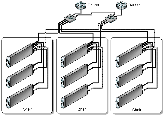
FIGURE 1-2 illustrates nine shelves connected using a combination of distribution switches and internal SSC switches. Note that the SSC0 versus SSC1 fabric correspondence is preserved throughout the Layer 2 network, and that the fabrics are interconnected at the distribution switch level. In asymmetrical (capacity and hops) topologies like the one shown, it is also appropriate to house the content load balancing blades in shelves directly connected to the distribution switches.
Routers are shown for completeness as they represents the boundary of the Layer 2 network on the path towards the service clients.

The SSL proxy blade is a companion product to the Sun Fire B10n blade, and as such its role is briefly described in this section. SSL proxy blades are used to:
For every service the content load balancer can be configured with one or more SSL proxy blades supporting the SSL sessions of the given service. SSL requests are delegated by the content load balancer and processed after decryption. Outbound encryption requests are directed from the servers to the corresponding SSL proxy blade without going through the content load balancing blade.
The content load balancing blade, along with its server-side module, are responsible for the appropriate path selection, failover, and VLAN tag selection for SSL traffic. The resulting functionality is summarized by:
This administration guide covers the configuration of SSL services at the content load balancing blade. Refer to the Sun Fire SSL Proxy Blade Administration Guide for more information.
The service availability obtainable from a given system is a function of the intrinsic failure rates of its components and the automatic failover capabilities of the system itself. A system designed around Sun Fire B1600 blade system product family has the following service failover aspects:
1. Server failover - This is the ability of any load balancer to remove non-responsive servers from service groups so that new requests go to functional servers. This capability is based on the server-monitoring function.
2. Path failover - This is the ability of the system to use an alternate network path whenever the current path does not appear to work, because of cable, switch, link, or end-point faults. This type of failover tends to be transparent, in the sense that session state at all endpoints is still valid and usable.
3. Blade failover - This is the ability to deploy content load balancing blades in high availability (HA) pairs that monitor each other. For a given service one of the load balancing blades is a standby blade, identically configured to the active blade, and responsible for taking over in if the active blade fails. SSL devices do not monitor each other, and their failover is rather controlled by the load balancing blade monitoring them as if they were servers.
The system designer can decide which level of failover to design into the system:
The use of VLANs within the Sun Fire B1600 blade platform provides the ability to separate traffic into logical groups on the same Ethernet switch fabric. The use of VLANs is preferred for separation between data and management traffic and when using the Sun Fire B10p SSL proxy blade to create logical separation of client side traffic (between the specialty network blades and the switch uplinks) from the server side traffic (between the specialty network blades and the servers).
VLANs are configured at the SSC switches to create logical groups of endpoints that can communicate as if they were on the same LAN. VLANs also prevent or restrict traffic between endpoints on separate VLANs. However, some environments might not support VLANs and they may either not be configured or they may be disabled. For the SSL proxy blades, VLANs are set to on by default, but they can be disabled with the set vlan filter disable command from the CLI interface. Refer to the Sun Fire B10p SSL Proxy Blade Administration Guide.
SSL proxy blades are configured to enforce the separation and direction of client side versus server side VLANs. The content load balancer and the SSL proxy blade cooperate to enforce the association between the operation performed (encryption versus decryption) with the allowed direction to and from the client VLAN.
Switches are responsible for VLAN separation enforcement, based on the VLAN identifiers present on Ethernet packets (explicitly or implicitly), as well as the physical ingress and egress switch ports involved.
The scope of the VLANs may be confined to the Sun Fire B1600 shelves while keeping all the uplinks VLAN untagged, or alternatively tagging may be enabled in the SSC uplinks to extend VLANs through the external switch infrastructure; in this case the VLAN ID assignment must be consistent with the external switch/router infrastructure VLAN assignments.
The minimal set of VLANs recommended for a proxy blade system are:
TABLE 1-4 presents how the different VLAN assignments and the Sun Fire content load balancer and proxy blade duties accomplish the desired security outcome.
The above actions, assigned to the different system components, must be complemented with the appropriate VLAN configuration at the SSC's and possibly other switches involved. The exact configuration scheme for the switches depends on how the uplinks are used and whether physical or VLAN separation is used.
VLANs can be extended to separate traffic for different user groups or tenants within the same Sun Fire B1600 blade platform.
In a multi-tenant environment it is appropriate to separate traffic based on the service 3-tuple. A VLAN identifier can be assigned by the content load balancing blade to identify the tenant (that is, the service owner), and thus ensure that its requests can only go to the specified tenant servers. In combination with the server side VLAN configuration, you can use VLANs to separate:
Although this book describes the administration of the Sun Fire B10n blade at the lowest possible level, you may want to approach system integration (that is via CLI and scripting), it is certainly possible and desirable to achieve higher levels of integration abstraction with other Sun software products like N1 deployment, and Sun ONE Web and Portal Servers.
When considering system integration, the main Sun Fire B10n blade considerations are:
The Sun Fire B10n blade has two levels of user access:
Some of the commands are accessible only with the right user access level. Even within a single user access level, there are different command modes.
The examples in this guide use the following format:
Copyright © 2004, Sun Microsystems, Inc. All rights reserved.