| C H A P T E R 1 |
|
Physical Specifications |
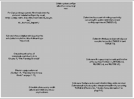
Sun Fire E25K/E20K systems come with various environmental requirements. Review the site preparation process flow diagram shown in FIGURE 1-1 as you begin to evaluate the needed requirements before your system installation.
 [ D ]
[ D ]
The Sun Fire E25K/E20K systems consist of two or more air-cooled cabinets that are configured to meet customer-specified requirements. Minimum configurations use one system cabinet, which houses system components and one customer selected
I/O expansion rack. System components include:
 Fireplane interconnect
All systems ordered are configured with a full complement of fan trays and power supplies, two System Control boards, and two SC peripheral boards. Processor and I/O boards are then ordered per the customer's specific system requirements.
Multiple cabinet configurations (FIGURE 1-2) would include additional customer selected I/O expansion racks with I/O cabling (customer-specified length). Customer selected I/O expansion racks house additional I/O disk or tape subsystems. Additionally, each I/O expansion rack contains AC distribution subsystems for use with the I/O subsystems.
Multiple cabinets may be placed side-by-side as long as the environmental specifications in Chapter 2 are met.
When determining the space, cooling, and power requirements, determine what system and I/O components will be used in your system. To begin the process of preparing your site for your Sun Fire E25K/E20K systems, record your configuration on the worksheet in TABLE 2-3.
The system cabinet may be located in any position within the system configuration.
Additional customer selected I/O expansion racks may be used, provided I/O cable length requirements are not compromised.
|
Note - Evaluate the system weight on both the raised floor system and the building structural system (see Section 1.3, Raised Floor Installations). The Sun Fire E25K system cabinet has a concentrated load weight of 628.4 lb (285.6 kg) per three-inch caster (within the allowable load for a typical computer room raised floor that is generally made of steel construction). The Sun Fire E20K system cabinet has a concentrated load weight of 547.9 lb (249.0 kg). |
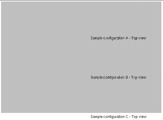
TABLE 1-1 lists the physical specifications for the Sun Fire E25K/E20K systems. Use TABLE 1-2 to calculate the weight of your system as various components are added.
|
Cabinet:
|
||
|
Access requirement for front
|
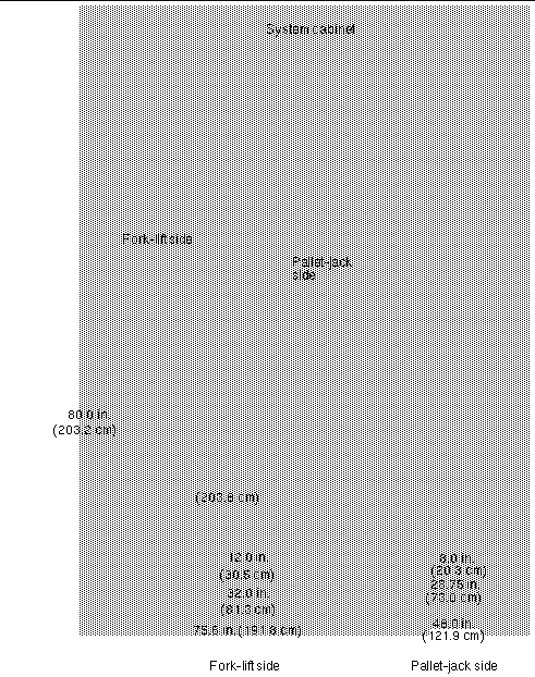
FIGURE 1-3 shows the dimensions of the Sun Fire E25K/E20K systems cabinet crate.
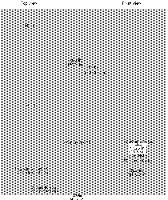
FIGURE 1-4 shows the dimensions of the Sun Fire E25K/E20K systems cabinet.
|
Note - There might be slight variances in some component weights depending on customer configurations. |
|
Note - The shipping pallet tie-down bracket holes in the front and rear of the lower chassis can also be used to hold-down or secure the system frame to the floor of your facility. |
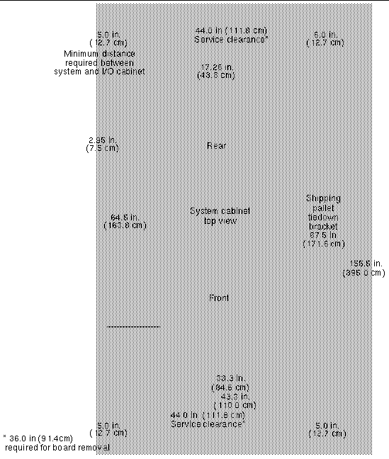
FIGURE 1-5 shows the clearance dimensions of the Sun Fire E25K/E20K systems cabinet.
For system cabinet electrical specifications and receptacle information, see TABLE 3-1.
 [ D ]
[ D ]
A raised floor system provides a convenient way to duct cooling air and to route power and communication cabling. Sun strongly suggests that the system be installed on a raised floor to ensure that optimal cooling is available to the system.
The computer room floor must be able to support the weight of the system cabinets (defined previously in TABLE 1-1). Each cabinet rests on four casters and four feet that concentrate the weight of the cabinet on a small surface area.
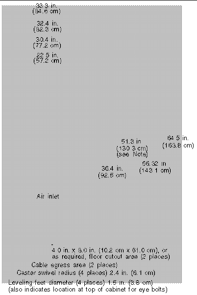
Place perforated floor panels or floor grilles near or directly under the base of the system. FIGURE 1-6 illustrates the floor cutouts for cables. Suggested locations for perforated floor panels or floor grilles are shown in FIGURE 2-2. Use the floor layout diagram of the proposed location for the system shown in FIGURE 1-6 to determine the exact area required for your system. Ensure cabinets are positioned so all casters and leveling feet are on solid raised-floor tiles.
Sun Microsystems suggests a minimum raised floor height of 24-36 in. (61.0-91.5 cm).
If you are not installing your system on a raised floor, ensure the cooling requirements specified in TABLE 2-2 can be met. Use cable covers to protect personnel from injury and protect cables from damage.
|
Note - If the cooling to the system is inadequate, automatic system shutdown can result. |
|
Note - Top frame members provide eye bolts at location shown (top of cabinet) using M12 x 1.75 bolts. |
 [ D ]
[ D ]
|
Note - In addition to the standard 4.0 in. X 8.0 in. (10.2 cm x 20.3 cm) floor cutout area (see dotted lines), any unused cable opening should be filled with a suitable material to block airflow. |
The cabinet has a concentrated load weight of 628.0 lb (285.5 kg) per three-inch caster (within the allowable load for a typical computer room raised floor). Review your facility floor weight requirements prior to moving the Sun Fire E25K/E20K system to its new location.
You can have various loads on a floor: static (concentrated, uniform, ultimate) or dynamic loads (rolling, and impact). Typical floating floors can handle approximately 1000 lb (454.6 kg) of concentrated load, 250 lb (113.6 kg) of uniform load, 2500 lb (1136.4 kg) of ultimate load, and 1000 lb (454.6 kg) of rolling load. These loads are estimates applied to a one-square-inch area. Review TABLE 1-3 for the Sun Fire E25K/E20K systems information on pounds per square foot on a building structure.
|
Note - The Sun Fire E25K/E20K systems require a shared-aisle space of 4.0 ft (121.9 cm). For the foot print weight, only unit dimensions and weight are calculated. For system-shared aisles of 4.0 ft (121.9 cm) (see FIGURE 2-3), assume two 48.0 in. (121.9 cm) tiles are at the front and rear of the system with a weight allocation of 50% for each system. |
There are also tiles such as ConCore2500 from Tate Access Floor Systems, Inc., that can take up to 2500 lb of concentrated load. If you have any questions concerning the structural capabilities of any floor, contact a qualified structural engineer.
For best performance, locate the cabinet over perforated floor tiles as indicated in Chapter 2, "Environmental Requirements", and the proposed configurations shown in FIGURE 2-2.
If your existing loading dock meets height or ramp requirements for a standard freight carrier truck, you can use a standard 60-inch pallet jack (at narrow end of pallet) to unload the system. Trucks can be between 48 ft (14.6 meters) and 61 ft (18.6 meters) long, 8.5 ft (2.6 meters) wide, and 14 ft (4.3 meters) high. If your loading dock does not meet these requirements, use a standard forklift (at wide side of pallet) or other means to unload the system, or request the system to be shipped in a truck with a lift gate. A standard forklift has a maximum outside tine dimension of 27 in. (68.6 cm) and a minimum inside tine dimension of 15 in. (38.1 cm).
An illustration of the system cabinet shipping crate and its dimensions are shown in FIGURE 1-3. A pallet jack is required to move each shipping crate to the system location.
Sun Microsystems suggests that you leave each system cabinet in its shipping crate until it reaches its unpacking destination. If the system does not fit through the planned access route, it can be partially disassembled after the unit has been removed from the crate. To accommodate the tight space availability, the side panels can be removed. This reduces the width of the system cabinet to 32.0 in. (81.3 cm) from its original width of 33.3 in. (84.6 cm).
The entire access route to your computer room should be free of raised patterns that can cause vibration. In addition, the strength of the perforated tiles should be verified. It is common to see damaged floor tiles in delivery paths because of the repeated rolling loads. It is suggested that the entire raised-floor delivery path be protected with material such as heavy particle board or another material of similar strength.
|
Note - Any path in the access route must not have an incline more than 10 degrees. |
Copyright © 2004, Sun Microsystems, Inc. All rights reserved.