| Sun Fire V490 Server Administration Guide
|
   
|
This appendix gives you reference information about the system's back panel ports and pin assignments.
Topics covered in this appendix include:
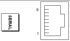
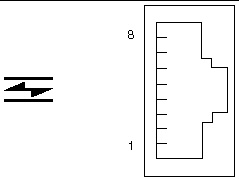
Serial Port Connector
The serial port connector is an RJ-45 connector that can be accessed from the back panel.
Serial Port Connector Diagram
Serial Port Connector Signals
|
Pin
|
Signal Description
|
Pin
|
Signal Description
|
|
1
|
Request To Send
|
5
|
Ground
|
|
2
|
Data Terminal Ready
|
6
|
Receive Data
|
|
3
|
Transmit Data
|
7
|
Data Set Ready
|
|
4
|
Ground
|
8
|
Clear To Send
|
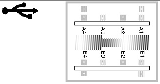
USB Connector
Two Universal Serial Bus (USB) connectors are located on the centerplane and can be accessed from the back panel.
USB Connector Diagram
USB Connector Signals
|
Pin
|
Signal Description
|
Pin
|
Signal Description
|
|
A1
|
+5 VDC
|
B1
|
+5 VDC
|
|
A2
|
Port Data0 -
|
B2
|
Port Data1 -
|
|
A3
|
Port Data0 +
|
B3
|
Port Data1 +
|
|
A4
|
Ground
|
B4
|
Ground
|
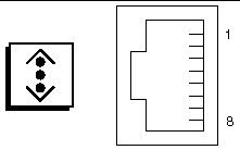
Twisted-Pair Ethernet Connector
The twisted-pair Ethernet (TPE) connector is an RJ-45 connector located on the system centerplane and can be accessed from the back panel. The Ethernet interface operates at 10 Mbps, 100 Mbps, and 1000 Mbps.
TPE Connector Diagram
TPE Connector Signals
|
Pin
|
Signal Description
|
Pin
|
Signal Description
|
|
1
|
Transmit/Receive Data0 +
|
5
|
Transmit/Receive Data2 -
|
|
2
|
Transmit/Receive Data0 -
|
6
|
Transmit/Receive Data1 -
|
|
3
|
Transmit/Receive Data1 +
|
7
|
Transmit/Receive Data3 +
|
|
4
|
Transmit/Receive Data2 +
|
8
|
Transmit/Receive Data3 -
|
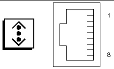
SC Ethernet Connector
The System Controller (SC) Ethernet connector is an RJ-45 connector located on the SC card and can be accessed from the back panel.
SC Ethernet Connector Diagram
SC Ethernet Connector Signals
|
Pin
|
Signal Description
|
Pin
|
Signal Description
|
|
1
|
Transmit/Receive Data0 +
|
5
|
Trandmit/Receive Data2 -
|
|
2
|
Transmit/Receive Data0 -
|
6
|
Trandmit/Receive Data1 -
|
|
3
|
Trandmit/Receive Data1 +
|
7
|
Trandmit/Receive Data3 +
|
|
4
|
Trandmit/Receive Data2 +
|
8
|
Trandmit/Receive Data3 -
|
SC Serial Connector
The System Controller (SC) serial connector is an RJ-45 connector located on the SC card and can be accessed from the back panel.
SC Serial Connector Diagram

SC Serial Connector Signals
|
Pin
|
Signal Description
|
Pin
|
Signal Description
|
|
1
|
Request To Send
|
5
|
Ground
|
|
2
|
Data Terminal Ready
|
6
|
Receive Data
|
|
3
|
Transmit Data
|
7
|
Data Set Ready
|
|
4
|
Ground
|
8
|
Clear To Send
|
FC-AL Port HSSDC Connector
The Fibre Channel-Arbitrated Loop port high-speed serial data connector is located on the centerplane and can be accessed from the back panel.
HSSDC Connector Diagram
HSSDC Connector Signal
|
Pin
|
Signal Description
|
Pin
|
Signal Description
|
|
1
|
Differential Data Output +
|
5
|
Optical Output Disable (optional)
|
|
2
|
Signal Ground (optional)
|
6
|
Differential Data Input -
|
|
3
|
Differential Data Output -
|
7
|
5V Power (+/-10%) (optional)
|
|
4
|
Mode Fault Detection (optional)
|
8
|
Differential Data Input +
|
| Sun Fire V490 Server Administration Guide
|
817-3951-10
|
|
Copyright © 2004, Sun Microsystems, Inc. All rights reserved.