| C H A P T E R 1 |
|
Basic RAID Concepts |
A redundant array of independent disks (RAID) offers major benefits in availability, capacity, and performance. Sun StorEdge 3000 family arrays provide complete RAID functionality and enhanced drive failure management.
This chapter covers the following concepts and planning guidelines:
The firmware of the Sun StorEdge 3000 family arrays is software that is installed or "flashed" into the array hardware before it is shipped. Later versions of the firmware can be downloaded and flashed at the customer site.
Different versions of controller firmware apply to various Sun StorEdge 3000 family arrays. Before downloading new firmware, be sure to check the README file or appropriate release notes to make sure you are upgrading to a supported version of the firmware for your array.
It is important that you run a version of firmware that is supported for your array. This manual covers the functionality for RAID firmware as follows:
The firmware versions share most of the same functions; however, the values might differ. Features which are only for SCSI or FC arrays are noted in the manual.
If you are downloading a Sun Microsystems patch that includes a firmware upgrade, the README file associated with the patch tells you which Sun StorEdge 3000 family arrays support that firmware release.
Illustrations in this guide demonstrate the steps you follow to use the firmware menu options and the results of those steps as they are displayed. The firmware menu options are the same for both SCSI and Fibre Channel (FC) arrays, so some of the illustrations describe SCSI arrays and other illustrations describe FC arrays. As a result, some of the device information you see on the screen differs slightly from what you see for your array.
Redundant array of independent disks (RAID) is a storage technology used to improve the processing capability of storage systems. This technology is designed to provide reliability in disk array systems and to take advantage of the performance gains offered by an array of multiple disks over single-disk storage.
RAID's two primary underlying concepts are:
In the event of a disk failure, disk access continues normally and the failure is transparent to the host system.
Increased availability, capacity, and performance are achieved by creating logical drives. A logical drive is created by combining independent physical drives. To the host, the logical drive appears the same as a local hard disk drive.
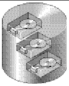
Logical drives can be configured to provide several distinct RAID levels, described in the remainder of this section.
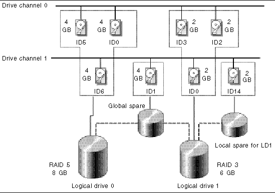
A local spare drive is a standby drive assigned to serve one specified logical drive. When a member drive of this specified logical drive fails, the local spare drive becomes a member drive and automatically starts to rebuild.
A global spare drive is not reserved for a single logical drive. When a member drive from any of the logical drives fails, the global spare drive joins that logical drive and automatically starts to rebuild.
The concept of a logical volume is very similar to that of a logical drive. A logical volume is composed of one or more logical drives. The logical drives in a logical volume do not have to be composed of the same RAID level.
While the ability to create and manage logical volumes remains a feature of Sun StorEdge 3000 Family FC and SCSI RAID arrays for legacy reasons, the size and performance of physical and logical drives have made the use of logical volumes obsolete. Logical volumes are unsuited to some modern configurations such as Sun Cluster environments, and do not work in those configurations. Avoid using them and use logical drives instead. For more information about logical drives, see Viewing and Editing Logical Drives.
A logical volume can be divided into a maximum of 32 partitions for SCSI arrays and 128 partitions for Fibre Channel arrays.
During operation, the host sees an unpartitioned logical volume or a partition of a partitioned logical volume as one single physical drive.
A SCSI channel can connect up to 15 devices (excluding the controller itself) when the Wide function is enabled (16-bit SCSI). Fibre Channel enables the connectivity of up to 125 devices in a loop. Each device has one unique ID.
A logical drive consists of a group of SCSI or Fibre Channel drives. Physical drives in one logical drive do not have to come from the same SCSI channel. Also, each logical drive can be configured for a different RAID level.
A drive can be assigned as the local spare drive to one specified logical drive, or as a global spare drive. A spare is not available for logical drives that have no data redundancy (RAID 0).
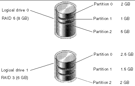
You can divide a logical drive or logical volume into several partitions or use the entire logical drive as a single partition.
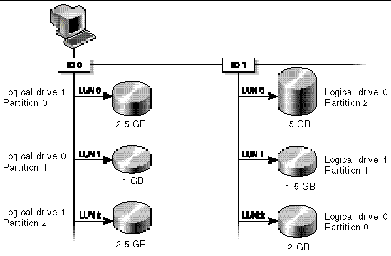
Each partition is mapped to LUNs under host FC or SCSI IDs, or IDs on host channels. Each FC or SCSI ID/LUN is seen as an individual hard drive by the host computer.
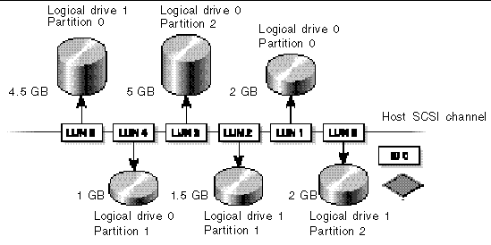
A RAID array has several advantages over non-RAID disk arrays:
There are several ways to implement a RAID array, using a combination of mirroring, striping, duplexing, and parity technologies. These various techniques are referred to as RAID levels. Each level offers a mix of performance, reliability, and cost. Each level uses a distinct algorithm to implement fault tolerance.
There are several RAID level choices: RAID 0, 1, 3, 5, 1+0, 3+0 (30), and 5+0 (50). RAID levels 1, 3, and 5 are most commonly used.
|
Note - The NRAID option that appears in some firmware menus is no longer used and is not recommended. |
|
Note - Drives on separate channels can be included in a logical drive, and logical drives of various RAID levels can be used to configure a logical volume. |
The following table provides a brief overview of the RAID levels.
Capacity refers to the total number (N) of physical drives available for data storage. For example, if the capacity is N-1 and the total number of disk drives in the logical drive is six 36-Gbyte drives, the disk space available for storage is equal to five disk drives (5 x 36 Gbyte or 180 Gbyte).
|
Note - The -1 refers to the amount of striping across the example six drives, which provides redundancy of data and is equal to the size of one of the disk drives. |
For RAID 3+0 (30) and 5+0 (50), capacity refers to the total number of physical drives (N) minus one physical drive (#) for each logical drive in the volume. For example, if the total number of disk drives in the logical drive is twenty 36-Gbyte drives and the total number of logical drives is 2, the disk space available for storage is equal to 18 disk drives (18 x 36 Gbyte or 648 Gbyte).
The advantages and disadvantages of different RAID levels are described in the following table.
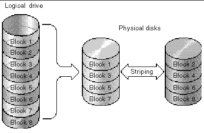
RAID 0 implements block striping, where data is broken into logical blocks and is striped across several drives. Unlike other RAID levels, there is no facility for redundancy. In the event of a disk failure, data is lost.
In block striping, the total disk capacity is equivalent to the sum of the capacities of all drives in the array. This combination of drives appears to the system as a single logical drive.
RAID 0 provides the highest performance. It is fast because data can be simultaneously transferred to and from every disk in the array. Furthermore, reads and writes to separate drives can be processed concurrently.
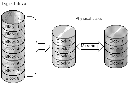
RAID 1 implements disk mirroring, where a copy of the same data is recorded onto two drives. By keeping two copies of data on separate disks, data is protected against a disk failure. If, at any time, a disk in the RAID 1 array fails, the remaining good disk (copy) can provide all of the data needed, thus preventing downtime.
In disk mirroring, the total usable capacity is equivalent to the capacity of one drive in the RAID 1 array. Thus, combining two 1-Gbyte drives, for example, creates a single logical drive with a total usable capacity of 1 Gbyte. This combination of drives appears to the system as a single logical drive.
|
Note - RAID 1 does not allow expansion. RAID levels 3 and 5 permit expansion by adding drives to an existing array. |
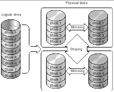
In addition to the data protection that RAID 1 provides, this RAID level also improves performance. In cases where multiple concurrent I/O operations are occurring, these operations can be distributed between disk copies, thus reducing total effective data access time.
RAID 1+0 combines RAID 0 and RAID 1 to offer mirroring and disk striping. Using RAID 1+0 is a time-saving feature that enables you to configure a large number of disks for mirroring in one step. It is not a standard RAID level option that you can choose; it does not appear in the list of RAID level options supported by the controller. If four or more disk drives are selected for a RAID 1 logical drive, RAID 1+0 is performed automatically.
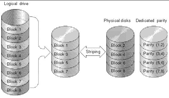
RAID 3 implements block striping with dedicated parity. This RAID level breaks data into logical blocks, the size of a disk block, and then stripes these blocks across several drives. One drive is dedicated to parity. In the event that a disk fails, the original data can be reconstructed using the parity information and the information on the remaining disks.
In RAID 3, the total disk capacity is equivalent to the sum of the capacities of all drives in the combination, excluding the parity drive. Thus, combining four 1-Gbyte drives, for example, creates a single logical drive with a total usable capacity of 3 Gbyte. This combination appears to the system as a single logical drive.
RAID 3 improves data transfer rates when data is being read in small chunks or sequentially. However, in write operations that do not span every drive, performance is reduced because the information stored in the parity drive must be recalculated and rewritten every time new data is written, limiting simultaneous I/O.
RAID 5 implements multiple-block striping with distributed parity. This RAID level offers redundancy with the parity information distributed across all disks in the array. Data and its parity are never stored on the same disk. In the event that a disk fails, original data can be reconstructed using the parity information and the information on the remaining disks.
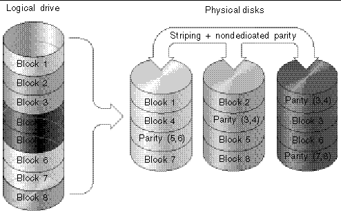
RAID 5 offers increased data transfer rates when data is accessed randomly or in large chunks, and reduced data access time during simultaneous I/O operations.
The following advanced RAID levels require the use of the array's built-in volume manager. These combination RAID levels provide the protection benefits of RAID 1, 3, or 5 with the performance of RAID 1. To use advanced RAID, first create two or more RAID 1, 3, or 5 arrays, and then join them.
The following table provides a description of the advanced RAID levels.
The external RAID controllers provide both local spare drive and global spare drive functions. A local spare drive is used only for one specified logical drive; a global spare drive can be used for any logical drive on the array.
The local spare drive always has higher priority than the global spare drive. Therefore, if a drive fails and global and local spares of sufficient capacity are both available, the local spare is used.
If there is a failed drive in the RAID 5 logical drive, replace the failed drive with a new drive to keep the logical drive working. To identify a failed drive, see Identifying a Failed Drive for Replacement.

|
Caution - If you mistakenly remove the wrong drive, you will no longer be able to access the logical drive because you have incorrectly failed two drives. |
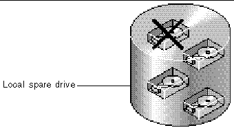
A local spare drive is a standby drive assigned to serve one specified logical drive. If a member drive of this specified logical drive fails, the local spare drive becomes a member drive and automatically starts to rebuild.
A local spare drive always has higher priority than a global spare drive. If a drive fails and a local spare and a global spare drive are both available, the local spare drive is used.
A global spare drive is available to support all logical drives. If a member drive in any logical drive fails, the global spare drive joins that logical drive and automatically starts to rebuild.
A local spare drive always has higher priority than a global spare drive. If a drive fails and a local spare drive and a global spare drive of sufficient capacity are both available, the local spare drive is used.
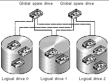
In FIGURE 1-13, the member drives in logical drive 0 are 9-Gbyte drives, and the members in logical drives 1 and 2 are all 4-Gbyte drives.
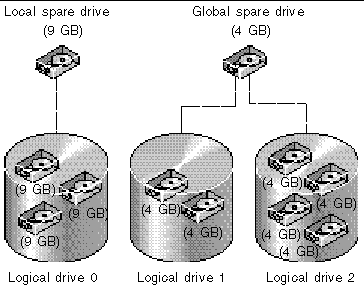
A local spare drive always has higher priority than a global spare drive. If a drive fails and a local spare and a global spare drive of sufficient capacity are both available, the local spare drive is used.
In FIGURE 1-13, it is not possible for the 4-Gbyte global spare drive to join logical drive 0 because of its insufficient capacity. The 9-Gbyte local spare drive is used for logical drive 0 once a drive in this logical drive fails. If the failed drive is in logical drive 1 or 2, the 4-Gbyte global spare drive is used immediately.
This section describes default configurations and certain controller limitations.
The entry-level configuration for an FC array uses only one controller. You can mirror two single-controller arrays using volume manager software on attached servers to ensure high reliability, availability, and serviceability (RAS).
You can also use dual-controller arrays to avoid a single point of failure. A dual-controller FC array features a default active-to-active controller configuration. This configuration provides high reliability and high availability because, in the unlikely event of a controller failure, the array automatically fails over to a second controller, resulting in no interruption of data flow.
Other dual-controller configurations can be used as well. For instance, at a site where maximum throughput or connecting to the largest possible number of servers is of primary importance, you could use a high-performance configuration. Refer to the Sun StorEdge 3000 Family Best Practices Manual for the Sun StorEdge 3510 FC Array for information about array configurations.
Be aware, however, that departing from a high-availability configuration can result in a significant decrease in the mean time between data interruptions. System downtime, however, is not impacted as severely because the time required to replace a controller, if one is available, is only about five minutes.
Regardless of configuration, customers requiring high availability should stock field-replaceable units (FRUs) such as disk drives and controllers on-site. Your FC array has been designed to make replacing these FRUs easy and fast.
The following controller functions describe the redundant controller operation.
The two controllers continuously monitor each other. When a controller detects that the other controller is not responding, the working controller immediately takes over and disables the failed controller.
An active-to-standby configuration is also available but is not usually chosen. By assigning all the logical configurations of drives to one controller, the other controller stays idle and becomes active only if its counterpart fails.
In a single-controller configuration, it is important to keep the controller as the primary controller at all times and to assign all logical drives to the primary controller. The primary controller controls all logical drive and firmware operations. In a single-controller configuration, the controller must be the primary controller or the controller cannot operate.
The secondary controller is only used in dual-controller configurations for redistributed I/O and for failover.
The Redundant Controller feature (reached by choosing "View and Edit Configuration Parameters  View and Edit Peripheral Devices
  Set Peripheral Device Entry") must remain enabled for single-controller configurations. This preserves the default primary controller assignment of the single controller.
The battery LED (on the far right side of the controller module) is an amber LED if the battery is bad or missing. The LED blinks green if the battery is charging and is solid green when the battery is fully charged.
The initial firmware screen also displays the battery status at the top of the initial screen where BAT: status displays somewhere in the range from BAD to ----- (charging), or +++++ (fully charged).
For maximum life, lithium ion batteries are not recharged until the charge level is very low, indicated by a status of -----. Automatic recharging at this point takes very little time.
A battery module whose status shows one or more + signs can support cache memory for 72 hours. As long as one or more + signs are displayed, your battery is performing correctly.
Your lithium ion battery should be changed every two years if the unit is continuously operated at 25 degrees C. If the unit is continuously operated at 35 degrees C or higher, it should be changed every year. The shelf life of your battery is three years.
For information on the date of manufacture and how to replace the battery module, refer to the Sun StorEdge 3000 Family FRU Installation Guide.
Unfinished writes are cached in memory in write-back mode. If power to the array is discontinued, data stored in the cache memory is not lost. Battery modules can support cache memory for several days.
Write cache is not automatically disabled when the battery is offline due to battery failure or a disconnected battery. You can enable or disable the write-back cache capabilities of the RAID controller. To ensure data integrity, you can disable the Write-Back cache option and switch to the Write-Through cache option by choosing "view and edit Configuration parameters  Caching Parameters."
Here are some questions that can help you plan your RAID array.
You have from 5 drives to 12 drives in your array.
Determine what capacity will be included in a logical configuration of drives. A logical configuration of drives is displayed to the host as a single physical drive. For the default logical drive configuration, see Default Logical Drives and RAID Levels.
The frequency of read/write activities can vary from one host application to another. The application can be an SQL server, Oracle server, Informix server, or other database server of a transaction-based nature. Applications like video playback and video postproduction editing require read/write operations involving very large files in a sequential order.
The RAID level setting you choose depends on what is most important for a given application--capacity, availability, or performance. Before revising your RAID level (prior to storing data), choose an optimization scheme and optimize the controller for your application.
The controller optimization mode can be changed only when there are no logical configurations. Once the controller optimization mode is set, the same mode is applied to all logical drives. Data stripe size is changed once the optimization method is changed. You cannot proceed with changing the optimization mode until data is backed up, all logical drives are deleted, and the array is restarted. Therefore, be careful in choosing an optimization mode for your controller.
|
Note - The controller factory defaults guarantee the optimal performance for most applications. |
A logical drive is a set of drives that have been combined into one logical drive to operate with a specified RAID level. It appears as a single contiguous storage volume. The controller is capable of grouping drives into eight logical drives, each configured with the same or different RAID levels. Different RAID levels provide varying degrees of performance and fault tolerance.
Spare drives allow for the unattended rebuilding of a failed physical drive, heightening the degree of fault tolerance. If there is no spare drive , data rebuilding has to be performed manually after replacing a failed drive with a healthy one.
Drives must be configured and the controller properly initialized before a host computer can access the storage capacity.
This section briefly outlines steps you can take to configure your array.
1. (Optional) Optimize the controller's parameters for your applications. For details on optimization modes, refer to Optimization Modes.
2. If a hard drive was connected after the controller completes initialization, choose "view and edit scsi Drives  Scan scsi drive" to enable the controller to recognize the newly added hard drive and to make it available to be configured as a member of a logical drive.
3. (Optional) Define any additional partitions for each logical drive. See Partitioning a Logical Drive.
4. (Optional) Add host IDs and more logical drives to create a maximum number of LUNs for your configuration. For more information see:
5. Map each logical drive and storage partition to a host ID/LUN. Refer to Mapping Logical Drive Partitions to Host LUNs. The host adapter recognizes the system drives after reinitializing the host bus.
6. Save your configuration profile to disk.
Copyright © 2004, Sun Microsystems, Inc. All rights reserved.