| C H A P T E R 1 |
|
Sun Fire V60x Compute Grid Rack System Hardware Overview and Installation |
The Sun Fire V60x Compute Grid rack system is shipped to your site fully assembled and cabled. This chapter is intended to familiarize you with the hardware in your Sun Fire V60x Compute Grid, and to provide installation and power-on instructions for the hardware.
The information in this chapter is organized into the following sections.
This guide provides important overview and reference information, as well as procedures for an initial installation. The following diagram indicates the high-level steps for installing the system and provides pointers to that information in this guide.
FIGURE 1-1 Installation Quick Path Flowchart
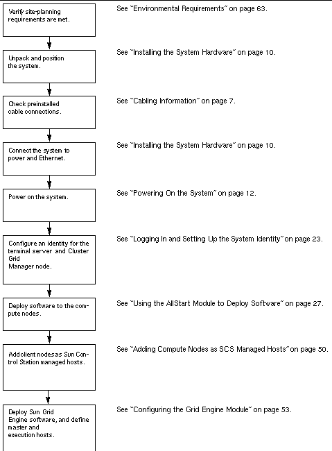
FIGURE 1-2 shows the Sun Fire V60x Compute Grid front and rear views. The front and rear doors are not shown. Components of the system are described in the sections that follow. For a cabling diagram, see Cabling Information.
FIGURE 1-2 Sun Fire V60x Compute Grid Front and Rear Views
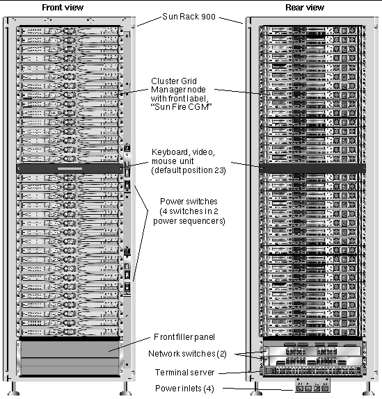
All of the Sun Fire V60x Compute Grid components and cabling are preinstalled in a Sun Rack 900. This rack is equipped with front and rear doors, and side covers.
All Sun Fire V60x Compute Grid cables are precut, routed, and terminated in locations that provide minimal excess cable without impeding component access or replacement.
The Sun Fire V60x Compute Grid is equipped with a full configuration of power distribution units and power sequencer units, which provide sufficient power outlets to cable all installed nodes. Each node has a separate 110/220 VAC power cord. The power cords are routed from the rear, with side-mounted outlet strips to minimize the impact on rear access to the components in the rack. There is minimal increase in load during rack power-on because all nodes are sequenced on in turn, minimizing the amplitude of power-on current spikes.
|
Note - The four power cords that connect each rack to the AC outlets at your site must be ordered separately so that the correct connectors for your location are defined. |
For more detailed information about the Sun Rack 900, refer to the Sun Rack documentation set that is shipped with your Sun Fire V60x Compute Grid.
The Sun Fire V60x Compute Grid uses two 24-port Gigabit Ethernet switches to communicate with the network. Each of the Sun Fire V60x nodes is connected from its Eth1 port to a switch port using a Cat 5 Ethernet cable. You can optionally dedicate up to four of each switch's ports to fiber-optic gigabit interface converters (GBICs).
The two network switches in each rack are interconnected with preinstalled, 1.8-feet (.5-meter), 32-Gbps stacking cables connected to their stacking ports. Each network switch has two stacking ports on its rear panel (the rear panel of the network switch faces the front of the system rack). When you order a system with multiple racks, the network switches must be interconnected across the racks. You can order 9.8-feet
(3-meter) stacking cables for this purpose. See Multiple-Rack System for more information.
For more detailed information about the network switches, refer to the third-party switch documentation that is shipped with your Sun Fire V60x Compute Grid.
All nodes in the rack and the network switches are connected via their serial console ports to a 48-port terminal server. The terminal server ports use consistent RJ-45 serial port wiring standards.
The terminal server can then be used to perform individual configuration functions remotely, if this is necessary. The terminal server provides normal Telnet access to a serial port using the telnet IP-address port-number protocol.
For more detailed information about the terminal server, refer to the third-party terminal server documentation that is shipped with your Sun Fire V60x Compute Grid.
The terminal server ports are assigned Telnet port numbers at the factory. TABLE 1-1 describes the port allocations.
One node in the system, called the Cluster Grid Manager (CGM) node, acts as a deployment and management host. After it is configured and given an identity by your system administrator, the CGM node deploys software and monitors system activities for the entire compute grid. In addition, it monitors the status of the grid jobs by communicating with the grid master node.
The CGM node is pre-installed with the operating system and Cluster Grid Manager software modules that enable the CGM node to act as the management host. For more detailed information about the system software components, see Sun Fire V60x Compute Grid Software Components Overview.
|
Note - The CGM node is identifiable by a label on the front bezel that is marked, "Sun Fire CGM." |
Your system administrator designates one node in the system to be the grid master node. This can be any node in the system other than the CGM node, because it is a dedicated management node rather than a managed host. All grid processes interact through this node, which typically acts as the queue master responsible for distributing jobs to the grid compute nodes.
If you install multiple rack configurations, no additional grid master nodes are needed; the grid master node of the first rack manages all subsequent racks.
The grid compute nodes act as slave nodes to the grid master node. The compute nodes accept tasks from the grid master node, process them to completion, then pass the results back to the grid master node for accumulation.
The number of compute nodes in the rack can be configured when the system is ordered. A fully configured rack can contain 32 compute nodes, including the grid master node. The minimum number of grid compute nodes that are supported is 2 and the maximum number is 128 (in 4 racks).
A keyboard, video monitor, and mouse (KVM) unit is included in the rack system and is precabled to the CGM node. This KVM is used for the initial configuration process by which the CGM node is configured with an IP address. After the initial configuration, the CGM node can be accessed through a remote serial connection to the terminal server.
The Sun Fire V60x Compute Grid is shipped with all required cables already installed, routed, and connected in a cable harness assembly.
The cables are labelled to make it easy to reconnect them if any come loose during shipping, or if components are subsequently replaced. Each cable-end is labeled with the device and port that it should connect to. For example, an Ethernet cable that connects Sun Fire V60x node #1 to network switch number one would have one end labeled, "V60x_1 eth0," and the other end labeled, "Switch1 1."
Serial cables used for terminal server connections are RJ-45 to RJ-45 rollover cables (8-core, Cat 5 type Ethernet). Network cables used for network switch connections are RJ-45 to RJ-45 straight cables (8-core, Cat 5/5e type Ethernet). See TABLE 1-2 for the wiring specifications for the two types of cables.
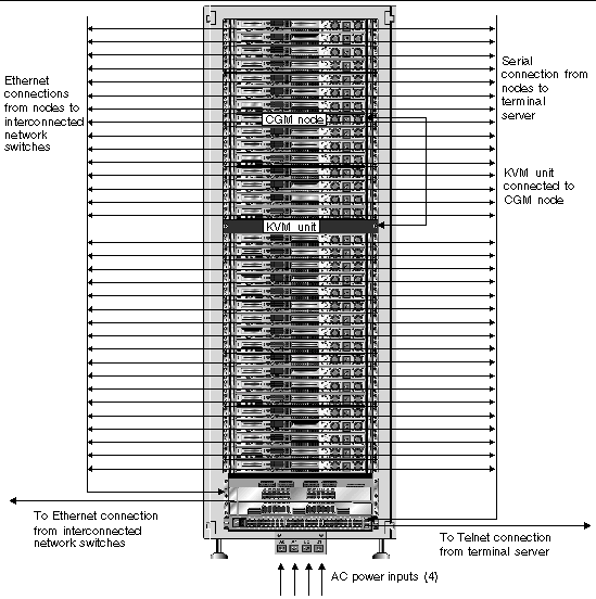
The diagram in FIGURE 1-3 shows how the components of a system are interconnected
.FIGURE 1-3 Single-Rack Cabling Diagram, Rear View
The two network switches in each rack are interconnected with preinstalled, 1.8-feet (.5-meter), 32-Gbps stacking cables connected to their stacking ports. Each network switch has two stacking ports on its rear panel (the rear panel of the network switch faces the front of the system rack). Refer to the network switch documentation that is shipped with your system for more information about switch stacking.
When you order a system with multiple racks, the network switches must be interconnected across the racks. You can order 9.8-feet (3-meter) stacking cables for this purpose.
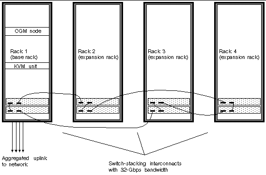
The diagram in FIGURE 1-4 represents a system with four fully-populated racks and a suggested stacking-cable configuration. The network switches and their stacking ports are represented. This configuration would enable interconnection of the data in all racks and enable an aggregated uplink to the network from the base rack.
FIGURE 1-4 Multiple-Rack Cabling Diagram
The installation site must meet specified requirements, which are described during the sales process with your organization. For reference, the environmental requirements are described in Appendix A.
1. Verify that your installation site complies with the environmental specifications as described in Appendix A.
Site-planning specifications are discussed as a part of the sales process, but are included in this guide for reference and verification.
2. Unpack each system rack from its shipping carton and position it at the installation location.
Refer to the "Sun Rack Unpacking Instructions" (816-6385), which is shipped with your system.
3. Mount each system rack, level the rack feet, and install the anti-tilt bar to the rack as desired.
Refer to the "Sun Rack Installation Guide" (816-6386), which is shipped with your system.
4. Check that all preinstalled cable connections between system components are firmly connected.
The cables are labelled to make it easy to reconnect them if any come loose during shipping, or if components are subsequently replaced. Each cable-end is labeled with the device and port that it should connect to. For example, an Ethernet cable that connects Sun Fire V60x node #1 to network switch number one would have one end labeled, "V60x_1 eth0," and the other end labeled, "Switch1 1."
5. Connect each system rack to four power outlets at your installation site, as follows.
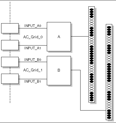
The system rack's power distribution system consists of four inputs (two sets of two: AC_Grid_0 and AC_Grid_1), two power sequencers (A and B), two power strips, and connecting cables. See FIGURE 1-5 for a diagram.
Each power input to the rack should be connected to a dedicated 20 Amp (North America) or 16 Amp (International) branch circuit. Individual outlets are grouped into sets of four.
Each individual rack outlet has a maximum current rating of 10 Amps. However, each outlet group has a maximum current rating of 10 Amps also. In other words, the total current for a group of four outlets cannot exceed 10 Amps.
FIGURE 1-5 Sun Rack 900 Power Distribution System Diagram
a. Turn off the power to the branch circuits that will supply power to the system.
b. Make sure both power sequencers in the rack are switched off.
c. Connect one end of each of the provided power cables to a branch circuit.
d. Connect the other end of each power cable to the rack's power input panel.
6. Connect the system to the network by connecting an Ethernet cable at your site to the system's network switch.
|
Note - If you are installing expansion racks in addition to the base system rack, connect the base system (the rack with the CGM node) to the network and connect the expansion racks to the base system rack as shown in FIGURE 1-4. |
1. Power on the system rack as follows.
a. Turn on power to the rack by switching on your site's branch circuits.
b. Turn on the four power sequencer switches on the front-right side of the rack.
Power is automatically applied to the terminal server, network switch, and KVM unit.
2. Verify that the power is on in the network switches, terminal server, and KVM unit.
It can take about a minute for the power indicator LEDs on the components to light.
3. Power on the CGM node, which is identifiable by its "Sun Fire CGM" label.
a. If the front bezel is attached to the node, remove it by grasping the finger-hole at the left side of the bezel and swinging it open to the right until it disengages.
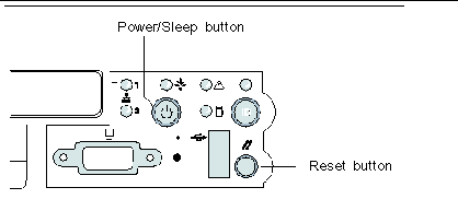
b. Press and release the power button on the right-front of the node. See FIGURE 1-6 for the location of the power button.
|
Note - If you are performing an initial installation, do not power on the other nodes of the system at this time. |
FIGURE 1-6 Sun Fire V60x Server Power and Reset Button Locations
4. Power on any expansion racks by repeating Step 1 and Step 3 for each expansion rack.
|
Note - If you are performing an initial installation, do not power on the other nodes in the expansion racks at this time. |
5. To continue with installation, go to Setting Up the Sun Fire V60x Compute Grid Software.
You can order the following hardware component options and add them to the system after the initial installation:
The tools that are needed to add or replace Sun Fire V60x Compute Grid components in the rack are listed here:
The Sun Rack Service Manual (816-6387) contains troubleshooting procedures, and removal and replacement procedures for the following rack parts:
The Sun Rack Service Manual is shipped with your system and is also available online at the following URL:
http:\\docs.sun.com
The software configuration tasks required when adding or replacing a node differ, depending on how the node will be used in the system. Use the procedure listed here that is appropriate.
If you replace a CGM node, you must reload all of the software that was preloaded on the original node at the factory.
If you need to replace a Sun Fire V60x node or a component inside the Sun Fire V60x node that acts as your CGM node, refer to the Sun Fire V60x and Sun Fire V65x Server Troubleshooting Guide and the Sun Fire V60x and Sun Fire V65x Server User Guide, which are included on the Sun Fire V60x and Sun Fire V65x Documentation CD (shipped with your system). These guides include instructions for removing and replacing Sun Fire V60x nodes in a Sun Rack 900, and for replacing internal node components.
After you have replaced the node or node component, reload the operating system and Cluster Grid Manager software using the procedures in the Sun Fire V60x Compute Grid Rack System Release Notes (817-3074).
If you need to replace a Sun Fire V60x node or a component inside the Sun Fire V60x node that acts as your grid master node, refer to the Sun Fire V60x and Sun Fire V65x Server Troubleshooting Guide and the Sun Fire V60x and Sun Fire V65x Server User Guide, which are included on the Sun Fire V60x and Sun Fire V65x Documentation CD (shipped with your system).
After you have replaced the node or node component, you must use the Sun Control Station software on the CGM node to redefine the replacement node as a managed host, and as either the grid engine master host or as an execution host. Refer to the Sun Control Station 2.0 Administration Manual, which is included on the Sun Control Station 2.0 Software CD (shipped with your system), and Configuring the Grid Engine Module.
If you need to replace a network switch, refer to the instructions that are shipped with the replacement switch for installation and configuration instructions.
Copyright © 2003, Sun Microsystems, Inc. All rights reserved.