| C H A P T E R 5 |
|
Removing and Replacing Miscellaneous Internal Components |

|
Caution - The procedures in this section are for qualified service engineers only. |

|
Caution - Before carrying out any of the procedures in this chapter, read Avoiding Electrostatic Discharge, and wear a properly grounded antistatic strap. |
|
Note - Illustrations might contain optional components that are not available on all standard configurations of the Netra 240 server. |
This chapter provides removal and replacement procedures for the following components:
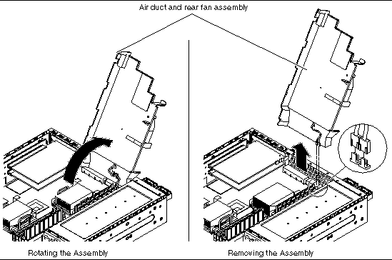
The air duct and rear fan assembly contains two fans, F0 and F1. The entire rear fan assembly should be replaced if one of these fans fail.
See Removing the Server Cover.
3. Open the rotating service module.
See Opening the Rotating Service Module.
4. Ensure that the server is properly grounded.
See Avoiding Electrostatic Discharge.
5. Determine if you want to gain access to the components beneath the air duct and rear fan assembly, or if you want to completely remove the assembly from the server (refer to FIGURE 5-1 for both sets of instructions).
a. Push the tab on the right of the assembly to the rear of the assembly and rotate the assembly up.
b. Unplug the two lower cables from the system board.
c. Dislodge the assembly from the rear supports and slide it out of the system.
1. Slide the air duct and rear fan assembly into position.
2. Plug in the two lower cables from the system board (FIGURE 5-1).
3. Rotate the assembly back in position and press down to snap the locking tab.
4. Close the rotating service module.
See Closing the Rotating Service Module.
See Installing the Server Cover.
There are eight DIMM slots on the system board, with four DIMM slots adjacent to each CPU socket. Because memory is installed as matched DIMM pairs, these slots are divided into two DIMM banks per CPU (see FIGURE 5-2 for their locations).
Therefore, CPU0 has four corresponding DIMM slots divided into two banks, Bank0 and Bank1. CPU1 has four corresponding DIMM slots divided into two banks, Bank0 and Bank1.
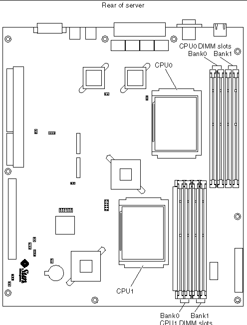
Memory is available in DIMM pairs. For a list of the available memory options, see Miscellaneous Internal Components.
See Removing the Server Cover.
3. Open the rotating service module.
See Opening the Rotating Service Module.
4. Ensure that the server is properly grounded.
See Avoiding Electrostatic Discharge.
5. Rotate the air duct and rear fan assembly up.
See Removing or Rotating the Air Duct and Rear Fan Assembly. Note that you only have to rotate the assembly up, not remove it from the server.
6. Press down on the latches at the sides of the memory socket (FIGURE 5-3).
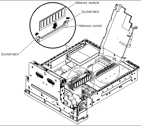
7. Remove the memory module from the socket.
When you install memory, follow these configuration rules:
1. Prepare the server for servicing, if you have not done so already:
See Removing the Server Cover.
c. Close the rotating service module.
See Opening the Rotating Service Module.
d. Ensure that the server is properly grounded.
See Avoiding Electrostatic Discharge.
e. Rotate the air duct and rear fan assembly up.
See Removing or Rotating the Air Duct and Rear Fan Assembly. Note that you only have to rotate the assembly up, not remove it from the server.
2. Locate the correct memory socket (FIGURE 5-3).
3. Ensure that the socket latches are open.
4. Press the memory module in the memory socket.
5. Press down until the socket latches snap into place.
6. Close the air duct and rear fan assembly.
See Installing or Closing the Air Duct and Rear Fan Assembly.
7. Close the rotating service module.
See Closing the Rotating Service Module.
See Installing the Server Cover.
The Netra 240 server supports one full-length 64-bit PCI card running at 33 MHz or 66 MHz (PCI0), and two half-length 64-bit PCI cards running at 33 MHz (PCI1 and PCI2). They are 3.3V (PCI 0) and 5V (PCI 1-2). The server can support a maximum of 25W per card, but no more than 45W spread over all three slots. The PCI cards are not hot-swappable.
|
Note - Add PCI cards to the Netra 240 server in order from PCI 0 to PCI 2. This corresponds to populating the PCI slots from bottom to top. |
The following procedures describe how to remove and install individual PCI cards into the Netra 240 server.
See Removing the Server Cover.
3. Open the rotating service module.
See Opening the Rotating Service Module.
4. Ensure that the server is properly grounded.
See Avoiding Electrostatic Discharge.
5. Completely remove the air duct and rear fan assembly.
See Removing or Rotating the Air Duct and Rear Fan Assembly.
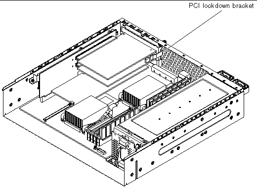
6. Using a No. 2 Phillips screwdriver, unscrew the PCI lockdown screw on the back of the server (FIGURE 5-4).

7. Remove the PCI lockdown bracket on the inside of the server (FIGURE 5-5).
8. Determine which of the PCI cards you are removing from the server.
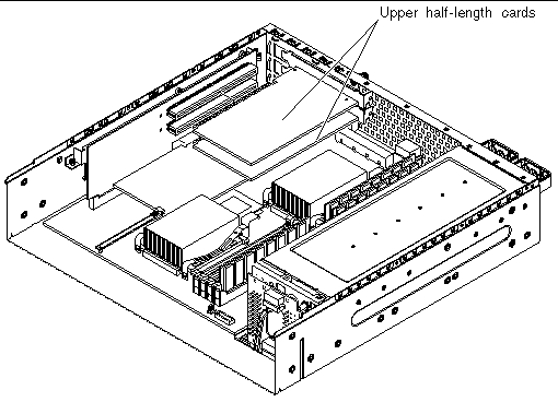
a. Pull up on the handle for the PCI card support and slide the support clear of the PCI card (FIGURE 5-7).
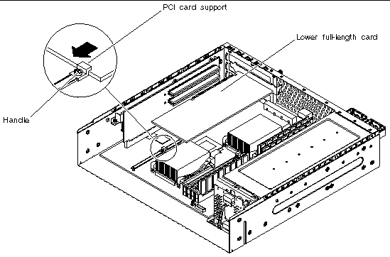
b. Unseat the PCI card from the connector and lift it out of the server (FIGURE 5-7).
1. Prepare the server for servicing, if you have not done so already:
See Removing the Server Cover.
c. Open the rotating service module.
See Opening the Rotating Service Module.
d. Ensure that the server is properly grounded.
See Avoiding Electrostatic Discharge.
e. Completely remove the air duct and rear fan assembly.
See Removing or Rotating the Air Duct and Rear Fan Assembly.
2. Insert the PCI card in the appropriate slot and press it firmly into its connector.
FIGURE 5-6 shows the slots for the upper half-length PCI cards, and FIGURE 5-7 shows the slots for the lower full-length PCI card.
3. If you are installing the lower full-length PCI card, pull up on the handle for the PCI card support and slide the PCI card support completely against the PCI card (FIGURE 5-7).
4. Reattach the PCI lockdown bracket and tighten the PCI lockdown screw (FIGURE 5-5 and FIGURE 5-4).
5. Install the air duct and rear fan assembly.
See Installing or Closing the Air Duct and Rear Fan Assembly.
6. Close the rotating service module.
See Closing the Rotating Service Module.
See Installing the Server Cover.
The power distribution board distributes power to the components in the Netra 240 server.
2. Disconnect the power input cables from both power supply units.
See Removing the Server Cover.
4. Open the rotating service module.
See Opening the Rotating Service Module.
5. Ensure that the server is properly grounded.
See Avoiding Electrostatic Discharge.
6. Disconnect the power distribution board wiring harness from the three connectors on the system board (FIGURE 5-8).
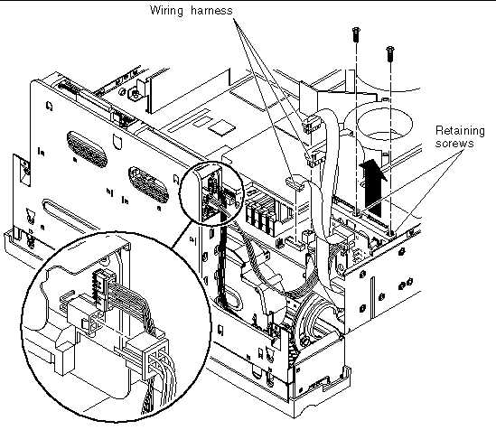
7. Disconnect the power distribution board cable from the SCSI interface board (FIGURE 5-8).
8. Pull the lever on the back of each power supply unit down (FIGURE 5-9).
This disconnects the power supply unit from the power distribution board.
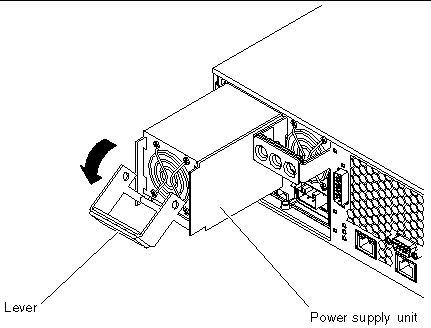
9. Slide each power supply unit part of the way out of the server chassis by pulling on the lever (FIGURE 5-9).
You do not have to completely remove the power supply units from the server.
10. Using a No. 2 Phillips screwdriver, unscrew the two retaining screws that hold the power distribution board in place (FIGURE 5-8).
11. Lift the power distribution board up and out of the server.
1. Insert the power distribution board in the server chassis (FIGURE 5-8).
2. Using a No. 2 Phillips screwdriver, secure the power distribution board to the server using the two retaining screws (FIGURE 5-8).
3. Connect the power distribution board cable to the SCSI interface board (FIGURE 5-8).
4. Connect the power distribution board wiring harness to the three connectors on the system board (FIGURE 5-8).

5. Insert the two power supply units in the power supply unit bays.
6. Slide each power supply unit into the server until you feel it engage with the power distribution board.
Ensure that the lever does not return to a vertical position until the power supply unit engages with the power distribution board. If the lever returns to vertical, the power supply unit does not engage correctly.
7. Press the lever up on each power supply unit until it clicks.
Returning the lever to a vertical position engages the power supply unit with the power distribution board inside the server.
8. Close the rotating service module.
See Closing the Rotating Service Module.
See Installing the Server Cover.
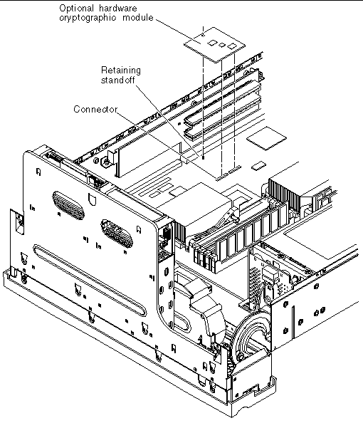
The optional hardware cryptographic module clips onto the Netra 240 server system board. For more information, see the documentation that is shipped with the optional hardware cryptographic module.
See Removing the Server Cover.
3. Open the rotating service module.
See Opening the Rotating Service Module.
4. Ensure that the server is properly grounded.
See Avoiding Electrostatic Discharge.
5. Remove all PCI cards from the PCI riser card assembly, if required.
See Removing a PCI Card.
6. Locate the retaining standoff that secures the hardware cryptographic module onto the system board (FIGURE 5-10).
7. Squeeze the retaining standoff to compress it.
8. Lift the hardware cryptographic module away from the chassis (FIGURE 5-10).
1. Press the retaining standoff into the system board.
2. Insert the hardware cryptographic module onto the retaining standoff and connector on the system board (FIGURE 5-10).
3. Press the hardware cryptographic module down to fully seat it.
4. Insert all PCI cards back into the PCI riser card assembly.
5. Install the air duct and rear fan assembly.
See Installing or Closing the Air Duct and Rear Fan Assembly.
6. Close the rotating service module.
See Closing the Rotating Service Module.
See Installing the Server Cover.
For information on configuring and using the hardware cryptographic module, refer to the documentation that is shipped with it.

|
Caution - The assembly might be very hot. Let it cool before beginning this procedure. |
See Removing the Server Cover.
3. Open the rotating service module.
See Opening the Rotating Service Module.
4. Ensure that the server is properly grounded.
See Avoiding Electrostatic Discharge.
5. Completely remove the air duct and rear fan assembly.
See Removing or Rotating the Air Duct and Rear Fan Assembly.
6. Remove all PCI cards from the PCI riser card assembly.
See Removing a PCI Card.
7. Using a No. 2 Phillips screwdriver, unscrew the two captive screws that secure the PCI riser card assembly to the system board (FIGURE 5-11).
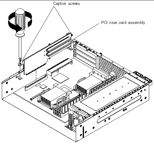
8. Pull the PCI riser card assembly straight up to detach it from the system board (FIGURE 5-11).
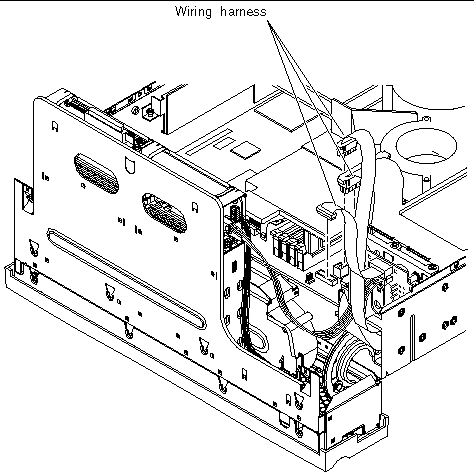
9. Disconnect the PDB wiring harness from the system board (FIGURE 5-12).
10. Lift the SCSI/IDE cable clamp out of the way (FIGURE 5-13).
The clamp has a green cap that is attached to the chassis, and holds the SCSI interface cable and the IDE cable.
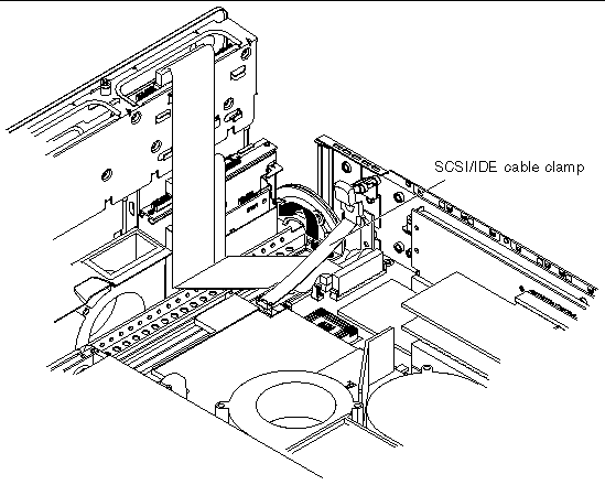
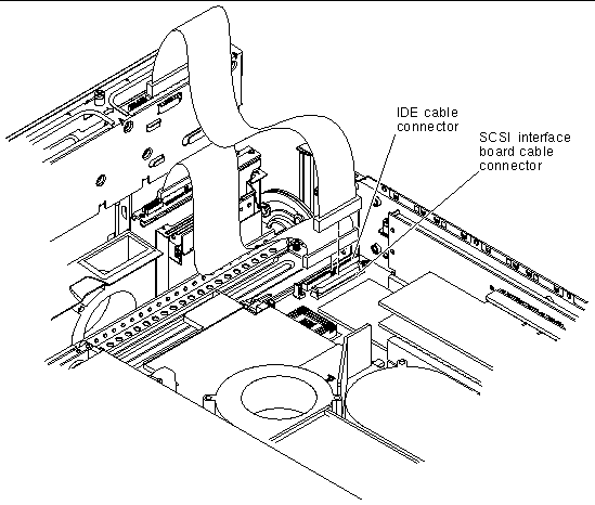
11. Disconnect the interface board SCSI and IDE cables from the system board (FIGURE 5-14).
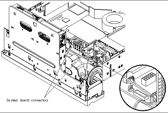
12. Disconnect the front fan assembly cables from the system board connectors (FIGURE 5-15).
13. Remove the Hardware Cryptographic Module.
See Removing the Hardware Cryptographic Module.
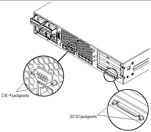
14. Unscrew and remove the DB-9 and SCSI jackposts on the server back panel (FIGURE 5-16).
15. Unscrew the two screws and remove the PCI card support (FIGURE 5-17).
16. Remove the ten screws that secure the system board to the bottom of the chassis (FIGURE 5-17).
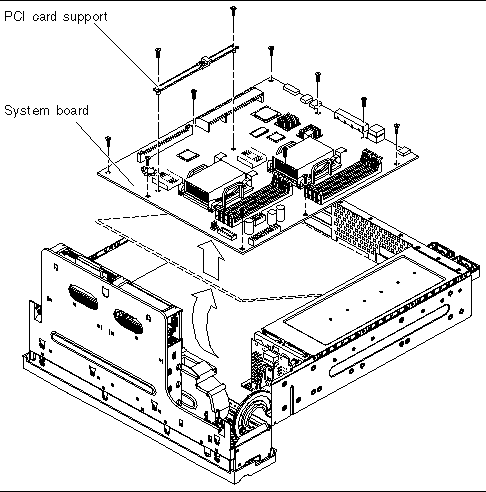
17. Lift the front of the system board slightly and slide the system board toward the front of the chassis so that the SCSI, Ethernet, and serial connectors come free from the chassis (FIGURE 5-17).
18. Lift the system board out of the chassis.
1. Place the replacement system board on a clean, static-free worktable.
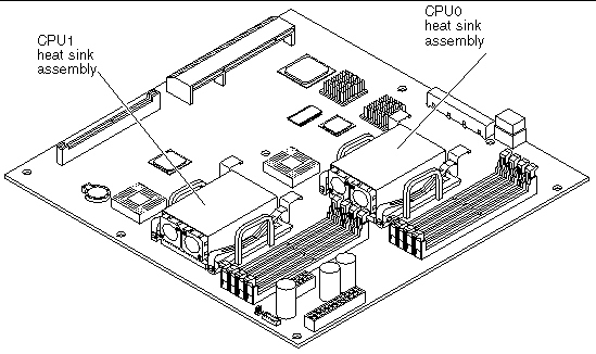
2. Locate the CPU heat sink assemblies on the system board (FIGURE 5-18).
Depending on your system board FRU, there are either one or two CPU heat sink assemblies.
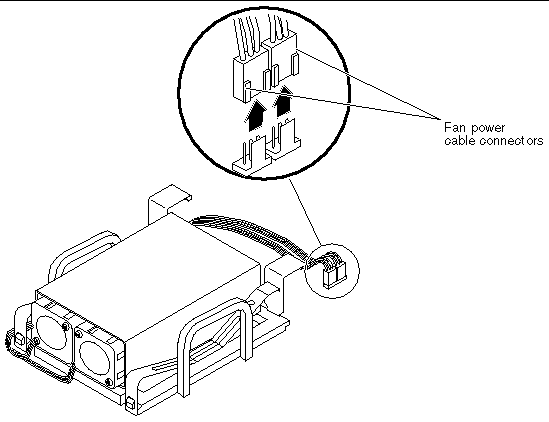
3. Detach the fan power cable connectors from the system board (FIGURE 5-19).
Follow the fan power cables from the fans to the cable connectors on the system board.
|
Note - The connectors for the CPU0 heat sink fans are labeled P0 F0 and P0 F1. The connectors for the CPU1 heat sink fans are labeled P1 F0 and P1 F1. |
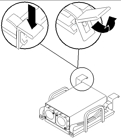
4. Unlock the heat sink from the CPU socket by first pressing down on the fasteners securing the heat sink assembly and then lifting them up (FIGURE 5-20).
Repeat this step for both fasteners on the heat sink.
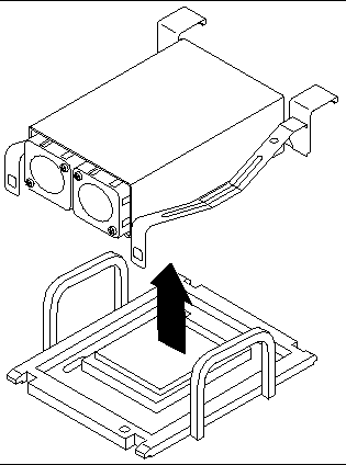
5. Carefully pull the heat sink up from the CPU socket (FIGURE 5-21).
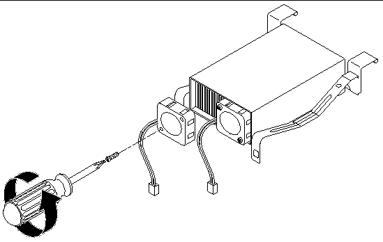
6. Using a No. 1 Phillips screwdriver, remove the screws securing the fans to the heat sink and remove the fans (FIGURE 5-22).
Two screws secure each fan. Set the fans and screws aside after removing them from the heat sink.
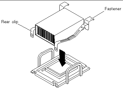
7. Carefully replace the heat sink on the CPU socket, and secure the heat sink by first attaching the rear clips and then pushing down the two front fasteners to the CPU socket (FIGURE 5-23).
8. If your system board has two CPU heat sinks, repeat Step 3 through Step 7 for the second heat sink.
9. Position the new system board so that the SCSI, Ethernet, and serial connectors are firmly positioned in their slots at the rear of the chassis and insert the board into the chassis (FIGURE 5-17).
10. Install all ten of the system board screws.
Do not put any screws in the holes for the PCI card slide retainer. These holes are identified by a circle printed around their circumference.
11. Replace the PCI card support and install the two screws that secure it (FIGURE 5-17).
Ensure that the arrow embossed on the slider points to the rear of the server.
12. Install and secure the DB-9 and SCSI jackposts to the server back panel (FIGURE 5-16).
13. Install the Hardware Cryptographic Module.
See Installing the Hardware Cryptographic Module.
14. Connect the front fan assembly cables to the system board connectors.
See FIGURE 5-15 to locate the system board connectors.
|
Note - Refer to the chassis label for an illustration of the correct routing of the cables. |
15. Connect the interface board SCSI and IDE cables to the system board.
See FIGURE 5-14 to locate the cables.
16. Press the SCSI/IDE cable clamp back down to secure the SCSI interface and IDE cables.
The cable clamp is attached to the chassis and has a green cap. See FIGURE 5-13 for the location of this clamp.
17. Connect the PDB wiring harness to the system board.
See FIGURE 5-12 to locate the wiring harness.
18. Place the PCI riser card assembly in position in the server (FIGURE 5-11).
a. Press down on the top of the assembly to fully seat it into the system board.
b. Tighten the two captive screws that secure the PCI riser card assembly to the system board (FIGURE 5-11).
19. Insert all PCI cards back into the PCI riser card assembly.
20. Install the air duct and rear fan assembly.
See Installing or Closing the Air Duct and Rear Fan Assembly.
21. Close the rotating service module.
See Closing the Rotating Service Module.
See Installing the Server Cover.
Copyright © 2004, Sun Microsystems, Inc. All rights reserved.