| Netra 240 Server Installation Guide
|
    |
The server has LED indicators associated with the server itself and with various components. The server status indicators are located on the bezel and repeated on the back panel. The components with LED indicators to convey status are the dry contact alarm card, power supply units, Ethernet port, and hard drives.
This appendix contains these sections:
|
Note - For additional information about these indicators, refer to the Netra 240 Server Service Manual (817-2699).
|
Front Panel Indicators
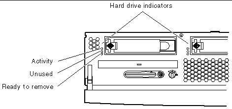
FIGURE A-1 shows the location of the front panel indicators, and TABLE A-1 provides information about the server status indicators. For information about the dry contact alarm card indicators, refer to the Netra 240 Server Service Manual (817-2699).
FIGURE A-1 Location of the Front Indicators

TABLE A-1 Server Status Indicators (Front and Rear)
|
Indicator
|
LED Color
|
LED State
|
Meaning
|
|
Activity
|
Green
|
On
|
The server is powered up and running the Solaris operating system.
|
|
|
|
Off
|
Either power is not present or the Solaris software is not running.
|
|
Service Required
|
Yellow
|
On
|
The server has detected a problem and requires the attention of service personnel.
|
|
|
|
Off
|
The server has no detected faults.
|
|
Locator
|
White
|
On
|
A continuous light turns on and identifies the server from others in a rack, when the ALOM setlocator command is used.
|
Hard Drive Indicators
The hard drive indicators can be seen when you lower the front bezel. FIGURE A-2 shows the location of the indicators, and TABLE A-2 provides information about these indicators.
FIGURE A-2 Hard Drive Indicators

TABLE A-2 Hard Drive Indicators
|
Indicator
|
LED Color
|
LED State
|
Component Status
|
|
Activity
|
Green
|
Flashing
|
Active SCSI transactions.
|
|
|
Off
|
No activity.
|
|
Unused
|
|
|
Reserved for later use.
|
|
Ready to remove
|
Blue
|
On
|
Ready to remove.
|
|
|
|
Off
|
Not ready to remove.
|
Rear Panel Indicators
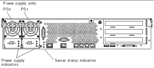
FIGURE A-3 shows the location of the power supply unit and rear server status indicators, and TABLE A-3 provides information about the power supply unit indicators. See TABLE A-1 for information about the server status indicators.
|
Note - FIGURE A-3 displays a DC-powered server. The rear panel indicators can be found in the same locations on an AC-powered server.
|
FIGURE A-3 Rear Indicators on the Netra 240 Server

TABLE A-3 Power Supply Unit Indicators
|
LED Color
|
LED State
|
Component Status
|
|
Green
|
On
|
Power is present and the power supply unit is active.
|
|
|
Off
|
Either the input power is not present, or the power supply unit has shut down due to an internal protection event.
|
|
Amber
|
On
|
The power supply unit has shut down due to an internal protection event and requires service attention.
|
|
Blue
|
Off
|
The power supply unit is operating normally.
|
|
|
On
|
The power supply unit is ready to be removed.
|
|
|
Off
|
The power supply unit is not ready for removal.
|
Ethernet Network Indicators
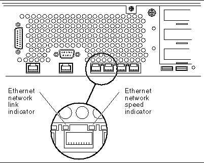
FIGURE A-4 shows the location of the Ethernet network indicators, and TABLE A-4 describes the network link indicators and TABLE A-5 describes the network speed indicators.
FIGURE A-4 Ethernet Network Indicators

TABLE A-4 Network Link Indicators
|
LED Color
|
LED State
|
Network Link Status
|
|
Green
|
On
|
Link is established.
|
|
|
Blinking
|
Link is transferring data.
|
|
|
Off
|
Link is not established.
|
TABLE A-5 Network Speed Indicators
|
LED Color
|
LED State
|
Network Speed Status
|
|
Green
|
On
|
The network link is established and running at its maximum supported speed.
|
|
|
Off
|
- If the network activity indicator is on, the network link is established but not running at its maximum supported speed.
- If the network activity indicator is off, network link is not established.
|
| Netra 240 Server Installation Guide
|
817-2698-12
|
    |
Copyright © 2004, Sun Microsystems, Inc. All rights reserved.


