| C H A P T E R 2 |
|
Installing the Chassis |
This chapter describes the steps necessary to install and set up the Netra CT 820 server. It includes instructions on unpacking, rackmounting, and making power connections.
You will need the following tools to install, remove, or replace most of the components in a Netra CT 820 server:
Check the shipping carton for damage. If the shipping carton and contents are damaged, notify the carrier and Sun Microsystems for an insurance settlement. Retain the shipping carton and packing material for inspection by the carrier. Obtain authorization before returning any product to Sun Microsystems. Contact your local Sun Microsystems sales representative for more information.
The Netra CT 820 server is shipped fully assembled and tested. The baseline configuration and most common options are listed below. Your system might differ from the system described in this manual.
 [ D ]
[ D ]
 [ D ]
[ D ]
|
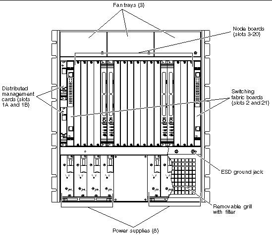
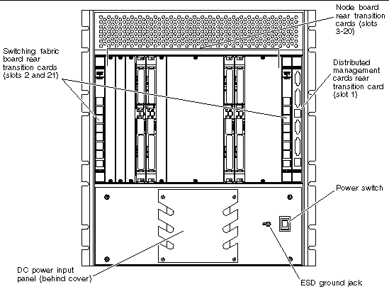
Note - ESD ground jacks are located at the front and rear of the system. To protect system components from static shock when handling them, wear a wrist strap plugged into the most convenient ESD ground jack. See FIGURE 2-1 and FIGURE 2-2 for ESD ground jack locations. |
Before installing and using the Netra CT 820 server, ensure that all cover panels are in place and that all component slots are populated with a component or covered with a blank filler panel.

|
Caution - Failure to cover open slots could cause overheating of power supplies, boards, or other components, and could damage the system. |
The Netra CT 820 server fits standard 19-inch EIA racks. Mounting flanges are attached to the front of the enclosure to facilitate front mounting. The flanges can be repositioned for center-mounting the enclosure.
This system is intended for stationary mounting in a rack designed to meet the physical strength requirements of NEBS GR-63-CORE and NEBS GR 487. Be sure to mount the system in a way that ensures even weight distribution in the rack. Uneven mechanical loading can result in a hazardous condition. Secure all mounting bolts when installing the enclosure to the frame or rack.
The maximum ambient temperature at which a factory-configured Netra CT 820 server should operate is 55°C (131°F) at 5% to 85% relative humidity (see Appendix A for details). The operating ambient temperature inside the enclosure might be greater than the room's ambient temperature if the system is installed with its ventilation intakes near another system's exhaust or in a closed or multiunit rack assembly. Install the system in an environment compatible with this recommended maximum ambient temperature. Due to the modular design of the system, components might be installed that alter the system's operating requirements. Please refer to product-specific documentation for the maximum recommended ambient temperature for individual components.
Safe operation of the Netra CT 820 server is dependent on the 250LFM/slot of forced-air cooling provided by the system's cooling fans. Be sure to install the system in an environment that does not compromise this recommended minimum airflow requirement.
1. Disconnect all power sources and external connections and cables prior to installing or removing the system from a rack.
2. Select a position in the rack that does not interfere with other equipment and that provides safe weight distribution.
3. Ensure that the area around the Netra CT 820 server's intake and exhaust vents are clear of obstructions for efficient cooling.
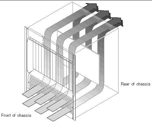
The intake should be away from another system's exhaust. FIGURE 2-3 shows the proper airflow for the Netra CT 820 server.
 [ D ]
[ D ]
4. Secure the mounting flanges to the front or middle of the enclosure.
5. Place the enclosure in its intended location and line up the mounting holes on the Netra CT 820 server's flanges with the rack's mounting holes.
6. Bolt the enclosure to the rack.
Rack hardware is not included.
The power input panel configuration must match the voltage input configuration of the power supplies intended for use with the system.
The Netra CT 820 server must be connected to properly rated supplies. For permanently connected equipment, a readily accessible disconnect device should be incorporated in the building wiring installation. Circuit breakers should be rated to handle the current indicated in the input specifications listed on the product identification label at the rear of the Netra CT 820 server.
Refer to the Netra CT 820 Server Product Overview for more information about providing power to the Netra CT 820 server.

|
Caution - Always ensure that the system is properly grounded before applying power. When the system is plugged in, energy hazards are present on the midplane. Do not reach into the enclosure. |
1. Verify that the power switch is in the Off (O) position.
See FIGURE 2-2 for the power switch location.
2. Remove the service panel cover from the DC terminal block.
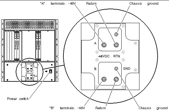
3. Attach the cables to the A and B terminal posts on the DC power input panel (FIGURE 2-4).
Conductors should be of adequate size to accommodate the maximum power output of the supplies (250W multiplied by the number of supplies powered from each feed), plus 20% for supply inefficiency. For each 2N configuration, each feed powers four power supplies, which equates to 1,000W per feed (plus 20% for supply inefficiency). To provide DC input power redundancy, connect both the A and B inputs to different redundant power sources. Refer to the Netra CT 820 Server Product Overview for more information about DC input power redundancy.

4. Replace the protective cover on the terminal block.
5. Complete the connection to the DC power source.
Copyright © 2004, Sun Microsystems, Inc. All rights reserved.