| C H A P T E R 2 |
|
Installing the Blade and Setting Up the System |
This chapter describes how to install the Sun Fire B10p SSL proxy blade hardware.
This chapter contains the following sections:
The instructions in this section are specific to installing the Sun Fire B10p SSL proxy blades into the Sun Fire B1600 blade chassis. However, these instructions are general, so be sure to refer to the documentation that came with your Sun Fire B1600 blade chassis.
|
Note - You must populate all 16 blade slots with either blades or filler panels before you apply power to the Sun Fire B1600 blade chassis. Do not leave any slots empty. |
1. Remove the filler panel from an unpopulated slot in a Sun Fire B1600 blade chassis or other supported system.
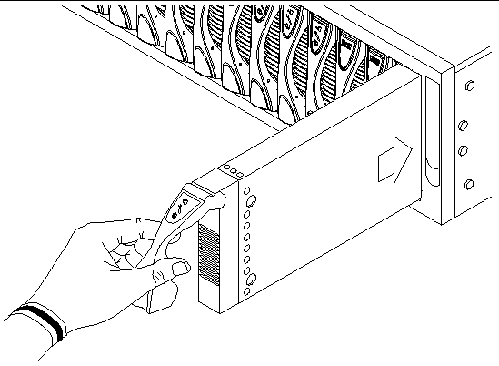
Insert your finger in the pull recess located in lower portion of the filler panel lever and pull gently to disengage the locking mechanism (FIGURE 2-1).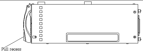
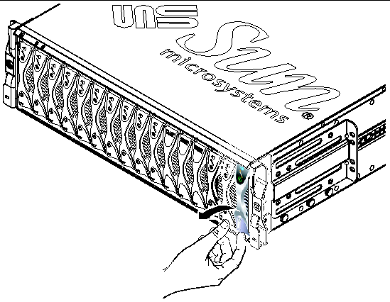
2. Pull the lever mechanism in a forward and upward motion, causing the filler panel lever to unlatch and eject the filler panel partially from the Sun Fire B1600 blade chassis (FIGURE 2-2).
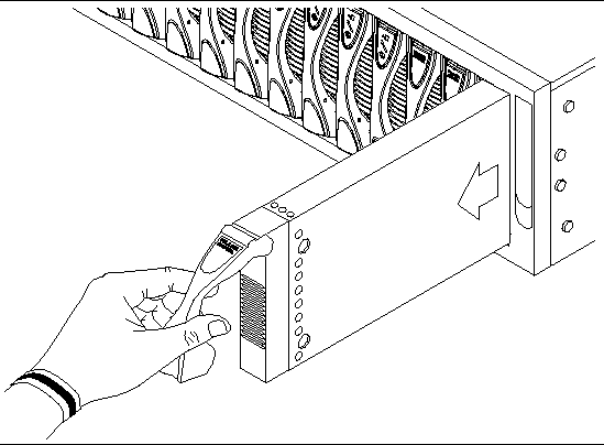
3. Pull the lever to remove the filler panel from the Sun Fire B1600 blade chassis (FIGURE 2-3).
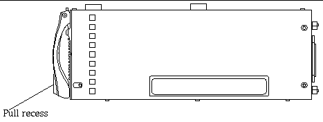
4. If required, open the blade lever by inserting a finger in the pull recess located in lower portion of the blade lever and pull the lever mechanism in a forward and upward motion, causing the lever to unlatch (FIGURE 2-4).
5. Align the Sun Fire B10p SSL proxy blade with an empty slot in the Sun Fire B1600 blade chassis.
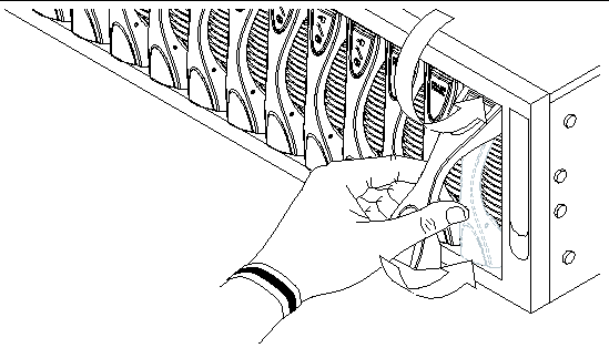
Ensure that the blade connector is facing towards the Sun Fire B1600 blade chassis, with the hinge point of the lever mechanism uppermost. Support the bottom of the blade with your free hand while lifting the blade up to the Sun Fire B1600 blade chassis (FIGURE 2-5).
6. Insert the SSL proxy blade into the system.
7. Gently push the blade into the slot until the blade latch ears, on top of the lever, are positioned in the Sun Fire B1600 blade chassis (FIGURE 2-6).
8. Complete the blade installation by closing the blade lever fully, which engages the blade into the Sun Fire B1600 blade chassis slot (FIGURE 2-6).
The green LED flashes as the blade powers up, and glows steadily when the blade is up and running.
Use the LEDs on the individual system components to determine if the system is operating normally. Monitor LEDs routinely on the:
The LEDs can be off, on, or flashing. When the fault LED is on (lit), this indicates that a fault has occurred in the component. A fault is any condition that is considered to be unacceptable for normal operation. When the fault LED is lit, you must take immediate action to clear the fault. You can only remove a hot-swappable component when the blue Removal OK LED is lit.
TABLE 2-1 lists the LED status codes for the following hot-swappable components:
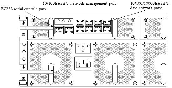
All ports are located at the back of the Sun Fire B1600 blade chassis. These connections are shown in FIGURE 2-7.
Note the location of the following ports:
|
Note - Twisted-pair cables must not exceed 328 feet (100 meters). |

Arranged as a 4x2 array, these RJ-45 ports provide the connection to the Combined Switch and Service Processor (CSSP). Each port has integral green Link Present and Link Active LED indicators.
|
Note - The Link Present indicator is always on the left, regardless of the orientation of the RJ-45 port. |
Viewing the Sun Fire B1600 blade chassis from the back, pin 1 of the RJ-45 serial port is on the left, and pin 8 is on the right.
 To power on a single blade, type:
Where S indicates the slot and n is the number of the slot containing the blade you want to power on. Valid slot numbers range from 0 to 15.
 To power on more than one blade, specify each blade in a space-separated list as in the following example:
 Use the showplatform command to verify the status of the SSL blade:
|
Note - Slots 14 and 15 show that the B10p SSL proxy blade is OK. |
The poweroff command attempts to shut down the operating system on a blade or blades in an orderly fashion. The command also prompts you to confirm that you intend to shut down the blade or blades you have specified.
 To poweroff a single blade, type:
Where n is the number of the slot containing the blade you want to power off.
 To poweroff more than one blade, specify each blade in a space-separated list, as in the following example:
The poweroff command attempts to shut down the SSL software on a SSL proxy blade in an orderly fashion. If this orderly shut down fails on a particular server blade, the poweroff command will not continue to power off the server blade.
 To force the SSL proxy blade to power off even if an orderly shut down has failed, include the -f option on the command-line, as in the following example:
|
|
When you run the poweroff command to power off a blade, you are prompted to confirm that you intend to power off the blade you have specified.
 To avoid receiving the confirmation prompt when you use the poweroff command, include the -y option on the command-line.
|
|
There are two ways to power a blade down to standby mode. You can use either the standbyfru command or the poweroff command.
 To power down a blade or blades to standby mode using the poweroff command, type:
Where n is the number of the slot containing the blade you want to power down. When a blade is in standby mode, the system service processor continues to monitor its operational state.
 To power down a blade for removal, type:
Where n is the number of the slot containing the blade you want to power down. When a server blade is powered off for removal, the OK to Remove LED is lit.
|
Note - You cannot use the -s option on the same command line as the -r option. |
If upgrading your software, please export any configurations, keys, and certificates first or you may lose this information after the software upgrade. See Chapter 6 for details on how to upgrade the software.
Copyright © 2004, Sun Microsystems, Inc. All rights reserved.