| C H A P T E R 1 |
|
Product Overview |
This chapter describes the Sun Fire B10p SSL proxy blade hardware and software, and lists both their features and the requirements for using them.
This chapter contains the following sections:
The Sun Fire B10p SSL proxy blade provide SSL handshake and encryption/decryption capabilities for the Sun Fire B1600 blade chassis. Designed specifically to optimize SSL processing, the custom hardware specialty blade can process SSL transactions many times faster than CPU-based SSL processing. The SSL proxy blade increases platform utilization by freeing system processors to complete other tasks, which enables maximum resource use, increased platform performance and availability of secure applications at lower costs.
The SSL proxy blade support for direct Proxy-to-Client response virtually eliminates the signal response back through the Sun Fire B10n content load balancing blade, which further speeds up response times and increases total capacity. Tamper-proof and centralized storage features as well as management capability of security keys and certificates also deliver higher levels of security and ease of management.
The primary performance parameter for SSL is the rate in which SSL sessions are established and the first file returned. This parameter is referred to as SSL sessions per second or transactions per second (TPS). The Sun Fire B10p SSL proxy blade has a maximum SSL sessions per second of 4000.
This product enables you to select the performance level that best fits your application. Up to four SSL proxy blade can be used in the same Sun Fire B1600 blade chassis. In the future, this maximum number may be increased. Check with your local Sun representative or the Sun.com web site for the latest configuration information.
The Sun Fire B10p SSL proxy blade deliver their high performance by utilizing optimized hardware engines and a tightly coupled embedded processor running a real time operating system. The code that runs on this processor is called the application software and can be updated using an FTP process.
In addition to the embedded processor, there is a micro controller called the blade support controller (BSC). The BSC is the primary interface to the Sun Fire B1600 service controllers (SCs) and performs the advanced lights out management (ALOM) functions for a given blade. These functions include powering on and off, and the resetting and monitoring functions. The code that runs on this device is called the BSC firmware and can be updated using the flashupdate command which involves using TFTP.
The Sun Fire B10p SSL proxy blade software components are as follows:
Check the following web site to ensure you have the latest software:
http://wwws.sun.com/software/download/network.html
There are two types of command line interfaces when working with blades in a Sun Fire B1600 system. The first type is the service controller or SC interface. The commands for this interface are detailed in the Sun Fire B1600 Blade System Chassis Software Setup Guide. You will recognize this interface by the sc> prompt.
The second type is the switch interface and is accessed with the console command. The individual blades in the chassis are accessed through the console command that is entered at the sc> prompt.
Where n is the blade slot you wish to access--for example:
Once the blade has been powered on and you are at the blade console prompt and have logged into the desired blade, you can administer the commands as outlined, in this case the Sun Fire B10p SSL Proxy Blade Adminstration Guide. You will recognize this interface by the CLI# prompt.
You can return to the sc interface by using the #. key sequence (that is, the hash (#) character followed by the dot (.) character).
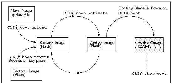
The Sun Fire B10p SSL proxy blade has the ability to hold three versions of the application software: an active image, a backup image, and a factory image. This capability ensures that you can revert to a safe image of the application software if a problem occurs with the current version or if a problem occurs when updating the software.
The typical operations associated with images are:
There is also a configuration file that holds the configuration data (see Configuration Storage). The operator will be prompted to overwrite the permanent configuration. It is important to backup the configuration of the system prior to the time when new software is uploaded.
FIGURE 1-1 shows the various images and how various CLI commands alter or copy them.
The BSC is the primary interface to the Sun Fire B1600 SCs. There is a single image stored in the micro controller that can be overwritten through the flashupdate process. If there is a problem during the BSC flashupdate process, the recovery is just a matter of repeating the update as the service controller software is managing the process.
Before using the Sun Fire B10p SSL proxy blade, make sure your system meets the following hardware and software requirements.
The following protocols are used for services or management functions:
The Sun Fire B10p SSL proxy blades are components within a larger system ultimately delivering highly available web services to a client population over an IP-based network. This section describes the role of such a highly integrated SSL proxy blade within the larger system.
The minimal set of components comprising the system encompasses:
Additionally, the system may have:
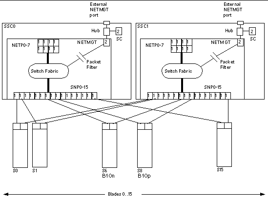
In general terms, the intra-shelf network topology formed by connecting the Sun Fire B1600 system components is either a single or a dual redundant Layer 2 topology with blades "one-arm" connected to each of the switch fabrics. The switch fabric is VLAN partitionable for strict traffic isolation. SSC switches and uplinks can be used for a simple inter-shelf network, or connected to external distribution switches for larger configurations.

FIGURE 1-2 shows the intra-shelf network, where an SSL proxy blade (shown in slot S8) can reside in any slot (S0 through S15) and connect to both SSC0 and SSC1 switch fabrics. The uplinks are labeled NETP0 through NETP7. The corresponding B10n content load balancing blade in slot S6 is shown for completeness.
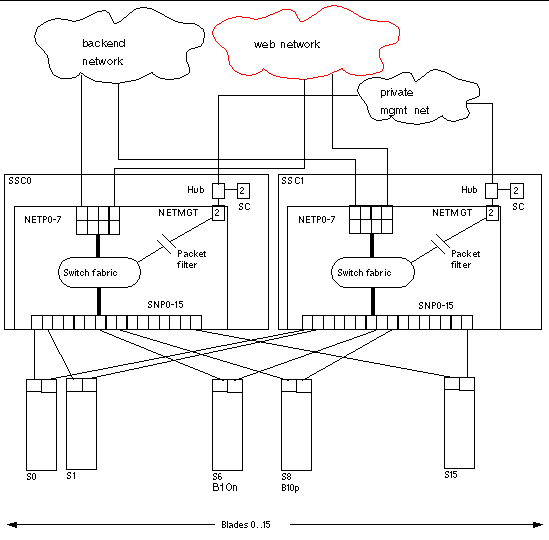
The numerals associated with each port (either 1 or 2), represent the VLAN numbers programmed into the system by default. These numbers indicate that there is one data VLAN (1), and one management VLAN (2). Further VLAN partitioning might be desirable as shown in FIGURE 1-3. The actual VLAN-ID assignment can be coordinated with the VLANs used in the external switches, or its scope can be limited to the internal switches, by keeping the uplinks as untagged VLANs.

The role of the B10n content load balancing blade is to present a set of highly available network services. These services can be transported over HTTP, HTTPS, TCP, or UDP, and are addressable through one or more virtual IP addresses (VIPs) that the content load balancing blade is responsible for:
VIPs are the routable IP addresses that clients obtain for the service though DNS lookups. A VIP address is owned by one content load balancer at a given time. VIPs are preserved through the content load balancer all the way to servers. Requests are directed to servers by re-writing their MAC addresses and their VLAN tags (and optionally the TCP/UDP port values).
A service is identified by a 3-tuple comprising the VIP, the Layer 4 protocol value (TCP or UDP), and the TCP/UDP destination port. A multi-homed service can be associated with more than one 3-tuple.
Whenever any of the services involve HTTPS, the Sun Fire B10n content load balancing blade content is responsible for involving the Sun Fire B10p SSL proxy blade as described later in this chapter.
To match the ample switching capacity of the SSC units in the Sun Fire B1600 blade chassis, the content load balancer solution is designed to direct server responses toward clients without passing through the content load balancer. This enables the outbound capacity of the system to scale in proportion to the number of servers deployed, and to exploit the natural web traffic asymmetry where most of the traffic is server outbound. Equivalently, HTTPS responses are passed through a direct flow from servers to the SSL proxy and on to clients, without involving the content load balancer.
To combine the uncompromised Layer 7 service performance with the direct server response, the content load balancer and SSL proxy blades rely on a software module in each server. This server module contributes to the solution's high degree of integration by providing key attributes, for example, path failover functionality.
The Sun Fire B1600 blade system switches are separate networks, leaving the system designer the option to connect them externally and create a symmetrically configured redundant system where every blade is dual-homed, or to leave the switches segregated for a system where full redundancy is either not necessary (or achieved elsewhere in the system hierarchy), and blades are single-homed to separate networks. You can also create intermediate configurations where critical blades (content load balancers, proxies, and so on) reside on shelves with dual switches, but blade servers do not.
When you connect SSC switches to create redundant paths, it is best if:
The above connections help ensure that the SSC switches are indeed leaf switches within the network infrastructure, and enable the content load balancer to use the shortest path within the redundant fabric (that is, the path that involves only one fabric).
Additionally, given the ingress request interactions between content load balancing and their corresponding SSL proxy blade or blades, it is beneficial to place them in the same shelf to minimize switching hops.
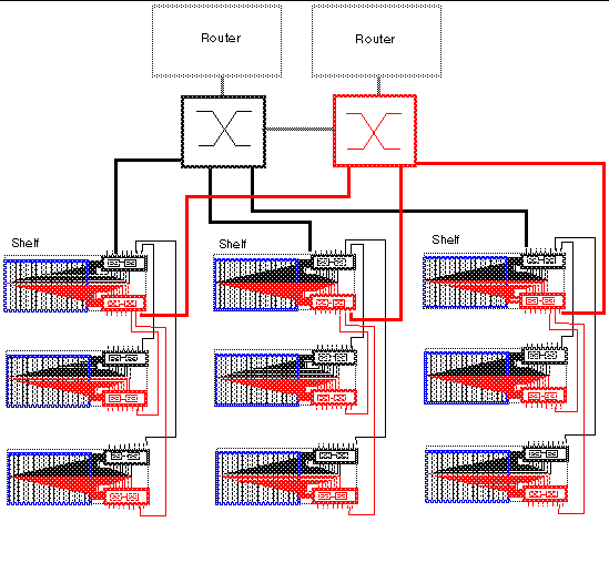
FIGURE 1-4 illustrates nine shelves connected using a combination of distribution switches and internal SSC switches. Note that the SSC0 versus SSC1 fabric correspondence is preserved throughout the Layer 2 network, and that the fabrics are interconnected at the distribution switch level. In asymmetrical (capacity and hops) topologies like the one shown in FIGURE 1-4, it is also appropriate to house the content load balancing blades in shelves directly connected to the distribution switches.
Routers are shown for completeness as they represent the boundary of the Layer 2 network on the path towards the service clients.

The Sun Fire B10p SSL proxy blade is a companion product to the Sun Fire B10n content load balancing blade, and the role of this blade is briefly described in this section. The SSL proxy blade performs the following:
For every service, the content load balancer can be configured with one or more SSL proxy blades supporting the SSL sessions of the given service. SSL requests are delegated by the content load balancer and processed after decryption. Outbound encryption requests are directed from the servers to the corresponding SSL proxy blade without going through the content load balancing blade.
The content load balancing blade, along with its server-side module, are responsible for the appropriate path selection, failover, and VLAN tag selection for SSL traffic. The resulting functionality is summarized by:
The service availability obtainable from a given system is a function of the intrinsic failure rates of its components and the automatic failover capabilities of the system itself. A system designed around Sun Fire B1600 blade system product family has the following service failover aspects:
1. Server failover - The ability of any load balancer to remove non-responsive servers from service groups so that new requests go to functional servers. This capability is based on the server-monitoring function.
2. Path failover - The ability of the system to use an alternate network path whenever the current path does not appear to work, because of cable, switch, link, or end-point faults. This type of failover tends to be transparent, in the sense that session state at all endpoints is still valid and usable.
3. Blade failover - This is the ability to deploy content load balancing blades in high availability (HA) pairs that monitor each other. For a given service one of the load balancing blades is a standby blade, identically configured to the active blade, and responsible for taking over if the active blade fails. SSL blades do not monitor each other, and their failover is rather controlled by the load balancing blade monitoring them as if they were servers.
The system designer can decide which level of failover to design into the system:
When using the Sun Fire B10p SSL proxy blade, VLANs must be used within the Sun Fire B1600 blade system. These VLANs are configured at the SSC switches to create logical groups of endpoints that can communicate as if they were on the same LAN. VLANs also prevent or restrict traffic between endpoints on separate VLANs.
The SSL proxy blade is configured to enforce the separation and direction of client side versus server side VLANs. The Sun Fire B10n content load balancing blade and the SSL proxy blade cooperate to enforce the association between the operation performed (encryption versus decryption) and the allowed direction to and from the client VLAN.
Switches are responsible for VLAN separation enforcement based on the VLAN Identifiers present in the Ethernet packets (explicitly or implicitly), as well as the physical ingress and egress switch ports involved.
The scope of the VLANs may be confined to the Sun Fire B1600 shelves while keeping all the uplinks VLAN untagged. Alternatively tagging may be enabled in the SSC uplinks to extend VLANs through the external switch infrastructure. In this case, the VLAN ID assignment must be consistent with the external switch/router infrastructure VLAN assignments.
The minimal set of VLANs recommended for a proxy blade system are:
TABLE 1-2 presents how the different VLAN assignments and the Sun Fire B10n content load balancing blade and the SSL proxy blade duties accomplish the desired security outcome.
The above actions, assigned to the different system components, must be complemented with the appropriate VLAN configuration at the SSCs and possibly at other switches involved. The exact configuration scheme for the switches depends on how the uplinks are used and whether physical or VLAN separation is used.
Although this book describes the administration of the Sun Fire B10p SSL proxy blades at the lowest possible level, you may want to approach system integration (that is, through CLI and scripting). It is certainly possible and desirable to achieve higher levels of integration abstraction with other Sun software products such as N1 deployment, and Sun ONE Web and Portal Servers.
Users must first log on to the command interface before access to any commands is allowed.
The SSL proxy blades support three access levels for initialization and configuration purposes. The three levels are: User, Administrator, and Security Officer (so), each with its own password. The privileges for each access level are described in the table below.
admin |
||
so |
The command descriptions (shown below) include the required access levels User, Administrator, or Security Officer for each command. Commands are not accessible if the access level of the command is higher than the access level of the logged in user.
Concurrent access to the SSL proxy blade is supported. Multiple users of any type can access the SSL proxy blade at a given time. This includes any combination of Telnet or console. The who and write commands, described below, can be used to arrange single so or admin access during delicate configuration tasks.
Some of the commands are accessible only with the right user access level. Even within a single user access level, there are different command modes:
The examples in this book use the following format:
Copyright © 2004, Sun Microsystems, Inc. All rights reserved.