| Sun XVR-1200 Graphics Accelerator Installation and User's Guide
|
   
|
Sun XVR-1200 Graphics Accelerator Specifications
|
This appendix provides I/O port specifications for the Sun XVR-1200 graphics accelerator.
I/O Port Specifications
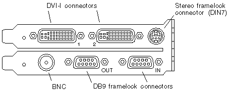
The external I/O ports are accessible through the I/O connectors on the Sun XVR-1200 graphics accelerator backplate (FIGURE B-1).
FIGURE B-1 Sun XVR-1200 Graphics Accelerator I/O Connectors
 [ D ]
[ D ]
DVI Video Connector
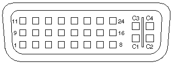
FIGURE B-2 and TABLE B-4 shows the Sun XVR-1200 graphics accelerator DVI connector and pinout signals. The DVI video connector is a 30-pin connector for a supported workstation monitor. The DVI video connector supports both analog and digital resolutions, but both cannot be used simultaneously from the individual DVI connector.
FIGURE B-2 Sun XVR-1200 Graphics Accelerator DVI Connector

TABLE B-1 Sun XVR-1200 Graphics Accelerator DVI Video Output Connector
|
Pin
|
Signal
|
|
1
|
TMDS Data2-
|
|
2
|
TMDS Data2+
|
|
3
|
TMDS Data2/4 Shield
|
|
4
|
No connect
|
|
5
|
No connect
|
|
6
|
DDC Clock (SCL)
|
|
7
|
DDC Bi-directional Data (SDA)
|
|
8
|
Analog vertical sync
|
|
9
|
TMDS Data1-
|
|
10
|
TMDS Data1+
|
|
11
|
TMDS Data1/3 Shield
|
|
12
|
No connect
|
|
13
|
No connect
|
|
14
|
+5V CD power
|
|
15
|
GND Return: +5V, Hsync, Vsync
|
|
16
|
Hot Plug Detect
|
|
17
|
TMDS Data0-
|
|
18
|
TMDS Data0+
|
|
19
|
TMDS Data0/5 shield
|
|
20
|
No connect
|
|
21
|
No connect
|
|
22
|
TMDS Clock shield
|
|
23
|
TMDS Clock+
|
|
24
|
TMDS Clock-
|
|
C1
|
Analog Red
|
|
C2
|
Analog Green
|
|
C3
|
Analog Blue
|
|
C4
|
Analog Horizontal Sync
|
|
C5
|
Analog GND Return: (analog R, G, B)
|
DB9 Video Connector
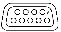
FIGURE B-3, TABLE B-2, and TABLE B-3 show the Sun XVR-1200 graphics accelerator DB9 connector and pinout signals. The DB9 connector is used to framelock two or more Sun XVR-1200 graphics accelerator subsystems for viewing over multiple displays. See Sun XVR-1200 Graphics Accelerator Framelock System.
FIGURE B-3 Sun XVR-1200 Graphics Accelerator DB9 Connector

TABLE B-2 Sun XVR-1200 Graphics Accelerator DB9 Connector-Multiview In
|
Pin
|
Signal
|
|
1
|
Slave sense
|
|
2
|
Ground
|
|
3
|
RefClk Input
|
|
4
|
RefClk Input
|
|
5
|
Ground
|
|
6
|
Release Input
|
|
7
|
Pixel Align Input
|
|
8
|
Ground
|
|
9
|
Done Input
|
TABLE B-3 Sun XVR-1200 Graphics Accelerator DB9 Connector-Multiview Out
|
Pin
|
Signal
|
|
1
|
3.3V (Fuse - 0.5A limit)
|
|
2
|
Ground
|
|
3
|
RefClk Output
|
|
4
|
RefClk Output
|
|
5
|
Ground
|
|
6
|
Release Output
|
|
7
|
Pixel Align Output
|
|
8
|
Ground
|
|
9
|
Done Output
|
Stereo Connector
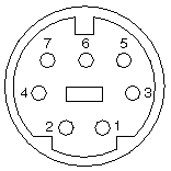
FIGURE B-4 and TABLE B-4 shows the Sun XVR-1200 graphics accelerator stereo DIN7 connector and pinout signals.
FIGURE B-4 Sun XVR-1200 Graphics Accelerator 7-Pin DIN Female Stereo Connector

TABLE B-4 Sun XVR-1200 Graphics Accelerator Stereo DIN7 Connector Pinout
|
Pin
|
Signal
|
|
1
|
Signal ground
|
|
2
|
5.0V (Fused, supplies up to 300mA, limited to 1.0A)
|
|
3
|
12.0V (Fused, supplies up to 300mA, limited to 1.0A)
|
|
4
|
Stereo sync
|
|
5
|
Framelock In
|
|
6
|
No connection
|
|
7
|
No connection
|
External Video Synchronization BNC Connector
The external video synchronization connector uses a 75-Ohm BNC male connector.
A 75-Ohm coax cable terminated with a female BNC connector is needed to connect to this port and provide a periodic signal to which the display system attempts to lock its vertical refresh rate.
The supported formats are:
- NTSC composite video
- PAL composite video
- TTL, LVTTL, or CMOS level compatible periodic signal (50 Hz 180 Hz), with a minimum low or high pulse or 100ns (TBV)
| Sun XVR-1200 Graphics Accelerator Installation and User's Guide
|
816-7386-12
|
   
|
Copyright © 2004, Sun Microsystems, Inc. All rights reserved.
 [ D ]
[ D ]


