| Clustered Database Platform 280/3 With Oracle9i and Sun Cluster HA Software Installation Guide |
| Clustered Database Platform 280/3 With Oracle9i and Sun Cluster HA Software Installation Guide |
| C H A P T E R 2 |
|
Clustered Platform 280/3 Hardware Installation |
This chapter contains the following topics:
The Clustered Platform 280/3 hardware must have two dedicated AC breakers. The cabinet should not share these breakers with other, unrelated equipment. The system requires two L30-R receptacles for the cabinet, split between two isolated circuits. For international installations, the system requires two Blue 32AIEC309 (international) receptacles.
If the cabinet is installed on a raised floor, cool conditioned air should be directed to the bottom of the expansion cabinet through perforated panels.
The Clustered Platform 280/3 system consumes power and dissipates heat as shown in TABLE 2-1.
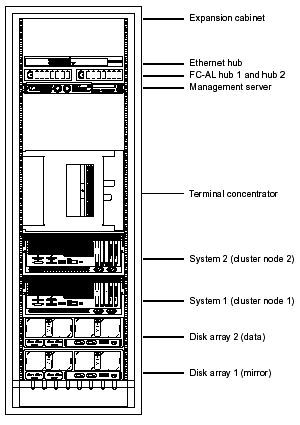
FIGURE 2-1 shows how the Clustered Platform 280/3 is arranged in the expansion cabinet. The hardware components are placed in the dual-power sequenced 72-inch expansion cabinets.
System components are cabled in the expansion cabinet to provide power and connections between the hardware components.
|
Note - The expansion cabinet arrangement complies with weight distribution, cooling, electromagnetic interference (EMI), and power requirements. |
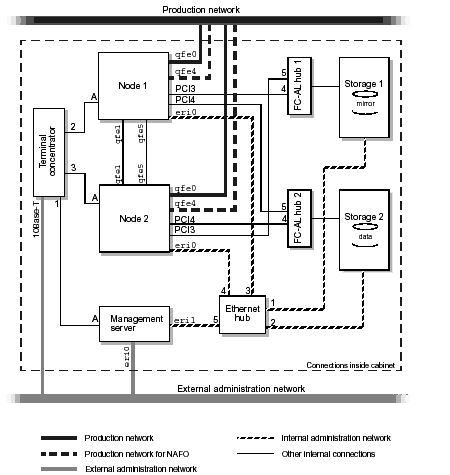
The Clustered Database Platform 280/3 system provides maximum connectivity in your enterprise network using the following network implementations:
 controllers (qfe4) to avoid a single point of failure (SPOF).
The Clustered Database Platform 280/3 system is shipped with the servers, hubs, and each of the arrays already connected in the cabinet. You do not need to cable the internal system components. The next chapter describes how to connect the Cluster Platform to your enterprise network.
For factory configured cable connections, see Appendix A.
This section contains a procedure for connecting the hardware at the customer site.
1. Connect the Clustered Database Platform 280/3 electrical cords to two separate power sources, but do not turn on the power to the Cluster Platform at this time.
See Power and Heating Requirements.
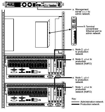
2. Connect the Clustered Database Platform 280/3 to your network(s) as described in the following steps and shown in FIGURE 2-3:
a. Connect the eri0 port of the management server to your administration network.
If you do not have an administration network, connect eri0 to your production network.
b. Connect the Ethernet port on the terminal concentrator to your administration network.
If you do not have an administration network, connect the Ethernet port to your production network.
c. Connect the qfe0 port on node 2 to your production network.
d. Connect the qfe4 port on node 2 to your production network.
This connection provides connectivity for network automatic failover (NAFO).
e. Connect the qfe0 port on node 1 to your production network.
f. Connect the qfe4 port on node 1 to your production network.
This connection provides connectivity for network automatic failover (NAFO).
| Clustered Database Platform 280/3 With Oracle9i and Sun Cluster HA Software Installation Guide | 816-4071-10 |
Copyright © 2002, Sun Microsystems, Inc. All rights reserved.
