Clustered Platform 280/3 Cabling
|
This appendix describes the arrangement of the cables in the Clustered Platform 280/3 system. This information is provided to assist in restoring the hardware to its original configuration after service.
TABLE A-1 Cluster Platform Cables
|
Cable
|
Part Number
|
Manufacturing part number
|
Quantity
|
|
RJ-45 Ethernet cable
|
1871A
|
530-1871
|
8
|
|
Fiber optic cable
|
n/a
|
537-1034
|
2
|
|
DB-25/RJ-45 serial cable
|
2151A
|
530-2151
|
2
|
|
Null Ethernet cable
|
3837A
|
530-2150
|
2
|
|
Serial port adapter
|
6973A
|
530-2889
|
1
|
|
Fiber optic cable
|
9715A
|
537-1020
|
4
|
|
Serial cable
|
9524A
|
530-9524
|
1
|
FIGURE A-1 Cluster Platform 280/3 Cabling
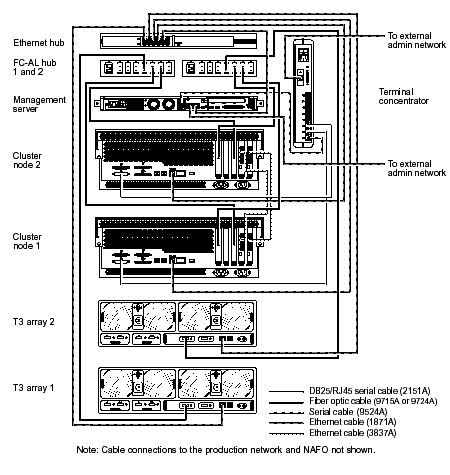
FIGURE A-2 Netra T1 200 Server (Management Server) Rear View Connectors
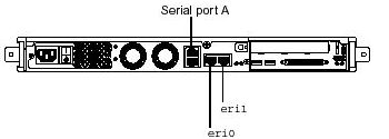
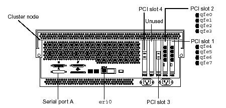
FIGURE A-3 Sun Fire 280R Server (Cluster Nodes) Rear View Connectors
The following table lists the connections you make when you install the Cluster Platform in your network environment as described in Chapter 2 and in FIGURE 2-2.
TABLE A-2 Connections Made On Site
|
From Device
|
From Location
|
To Customer Network
|
Cable Type
|
|
Management server
|
eri0
|
Administration network1
|
Ethernet
|
|
Terminal concentrator
|
Ethernet port
|
Administration network1
|
Ethernet
|
|
Node 1
|
qfe0
|
Production network
|
Ethernet
|
|
Node 1
|
qfe4
|
Production network
|
Ethernet
|
|
Node 2
|
qfe0
|
Production network
|
Ethernet
|
|
Node 2
|
qfe4
|
Production network
|
Ethernet
|
The following tables list factory configured cable connections.
TABLE A-3 Disk Array to Hub Connections
|
From Device
|
From Location
|
To Device
|
To Location
|
Cable Length/Type
|
|
Disk array 1 (mirror)
|
FC-AL port
|
FC-AL hub 1
|
Port 3
|
15 m/FC-AL
|
|
Disk array 2 (data)
|
FC-AL port
|
FC-AL hub 2
|
Port 3
|
15 m/FC-AL
|
|
Disk array 1 (mirror)
|
10BASE-T
|
Ethernet hub
|
Port 1
|
4 m/Ethernet
|
|
Disk array 2 (data)
|
10BASE-T
|
Ethernet hub
|
Port 2
|
4 m/Ethernet
|
TABLE A-4 FC100 Hub to Server Connections
|
From Device
|
From Location
|
To Device
|
To Location
|
Cable Length/Type
|
|
FC-AL hub 1
|
Port 4
|
Node 1
|
PCI slot 3
|
5 m/FC-AL
|
|
FC-AL hub 1
|
Port 5
|
Node 2
|
PCI slot 3
|
5 m/FC-AL
|
|
FC-AL hub 2
|
Port 5
|
Node 1
|
PCI slot 4
|
5 m/FC-AL
|
|
FC-AL hub 2
|
Port 4
|
Node 2
|
PCI slot 4
|
5 m/FC-AL
|
TABLE A-5 Management Server Connections
|
From Device
|
From Location
|
To Device
|
To Location
|
Cable Type
|
|
Management server
|
Serial port A
|
Terminal concentrator
|
Serial port 1
|
Serial
|
|
Management server
|
eri1
|
Ethernet hub
|
Port 5
|
Ethernet
|
|
Management server
|
eri0
|
See TABLE A-2
|
TABLE A-6 Terminal Concentrator Connections
|
From Device
|
From Location
|
To Device
|
To Location
|
Cable Type
|
|
Terminal concentrator
|
Serial port 1
|
Management server
|
Serial port A
|
Serial
|
|
Terminal concentrator
|
Serial port 2
|
Node 1
|
Serial port A
|
DB-25 serial/RJ-45
|
|
Terminal concentrator
|
Serial port 3
|
Node 2
|
Serial port A
|
DB-25 serial/RJ-45
|
|
Terminal concentrator
|
Ethernet port
|
See TABLE A-2
|
TABLE A-7 Node to Node Connections
|
From Device
|
From Location
|
To Device
|
To Location
|
Cable Length/Type
|
|
Node 1
|
PCI slot 2, qfe1
|
Node 2
|
PCI slot 2, qfe1
|
5 m/Null Ethernet
|
|
Node 1
|
PCI slot 1, qfe5
|
Node 2
|
PCI slot 1, qfe5
|
5 m/Null Ethernet
|
TABLE A-8 Ethernet Hub Connections
|
From Device
|
From Location
|
To Device
|
To Location
|
Cable Type
|
|
Ethernet hub
|
Port 1
|
Disk array 1 (node 1)
|
10/100 BASE-T port
|
Ethernet
|
|
Ethernet hub
|
Port 2
|
Disk array 2 (node 2)
|
10/100 BASE-T port
|
Ethernet
|
|
Ethernet hub
|
Port 5
|
Management server
|
eri1
|
Ethernet
|
|
Ethernet hub
|
Port 3
|
Node 1
|
eri0
|
Ethernet
|
|
Ethernet hub
|
Port 4
|
Node 2
|
eri0
|
Ethernet
|