| A P P E N D I X A |
|
Application Programmers' Interface |
The Application Programmers' Interface (API) provided with this software release is an interim API from Sun Microsystems, Inc. that can be used on Sun Platforms.
In the ATM environment, data is sent between hosts over Virtual Circuits (VCs). VCs are point-to-point (or point-to-multipoint) connections between two or more ATM hosts.
VCs can be created in one of two ways:
Manual configuration at each host and each intermediate network point, also known as Permanent Virtual Circuits (PVC)
ATM signalling, also known as Switched Virtual Circuits (SVC)
After the VC has been created, the application notifies the SunATM ba driver that it is sending and receiving data on the new VC.
If you are using a PVC, this is the only configuration required on the Sun host.
If you are using an SVC, there are two required actions:
|
Note - For historical reasons, Q.93B and Q.2931 are used interchangeably. |
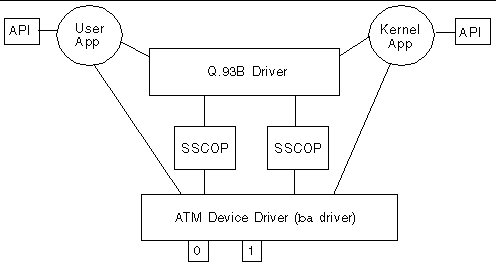
The architecture illustrated in FIGURE A-1 must be established on a SunATM system in order to perform Q.2931 signalling and send data over established connections. The ATM device driver, SSCOP modules, and Q.93B driver are "plumbed" at boot time. The task remaining for application developers is to create the connections between their application and the Q.93B and ATM device drivers.
Both the Q.93B and ATM device driver are STREAMS drivers; connecting to them is for the most part no different than connecting to other STREAMS drivers. The following sections describe the steps required to connect to each driver, use the drivers to establish ATM connections, and send data over those connections.
For examples of applications that use the SunATM API, see the sample programs installed in /opt/SUNWconn/atm/examples.
 [ D ]
[ D ]
The signalling API, called Q.2931 Call Control (qcc), consists of two sets of similar functions: one for applications running in the kernel and one for applications running in user space. Each set provides functions to build and parse Q.2931 signalling messages, which are required to set up and tear down connections.
One additional function assists applications in establishing appropriate connections to the Q.93B driver. q_ioc_bind associates a service access point (SAP) with the specified connection to the Q.93B driver. The driver uses the SAP to direct incoming messages to applications.
Use the open(2) system call to obtain a file descriptor to the driver. After opening the driver, q_ioc_bind should be called, associating in the Q.93B driver a service access point (SAP) with this application. Finally, if the application is a kernel driver, it should be linked above the Q.93B driver, using the I_LINK or I_PLINK ioctl (refer to the streamio(7) man page for information about this ioctl).
After connecting to the Q.93B driver, either by directly calling the functions as a user application or by having a setup program connect your application driver as described in the preceding section, the Q.93B driver is available to your application to establish switched virtual circuits (SVCs) using the Q.2931 signalling protocol. The Q.2931 message set is displayed in TABLE A-1.
The Q.93B driver is an M-to-N mux STREAMS driver. Multiple application programs can be plumbed above the driver, and multiple physical interfaces can be connected below Q.93B. Applications can access any or all of the physical interfaces, and messages received on the physical interfaces can be directed to any of the applications. To direct messages through the Q.93B driver, messages from applications must include a physical interface name to identify the outgoing interface and a SAP to identify the application to which the message should be directed on the receiving host.
Send messages to Q.93B by applications according to the format illustrated in FIGURE A-2; kernel applications use putnext(9f) to send the mblocks shown and user applications send two corresponding strbufs using putmsg(2).

The structure included in the M_PROTO mblock is defined as the qcc_hdr_t structure in the <atm/qcctypes.h> header file. In the second mblock, the Q.2931 header portion (9 bytes) of the Q.2931 message is blank and later filled in by the Q.93B driver. The application should also reserve 16 bytes at the end of the second mblock for the layer 2 (Q.SAAL) protocol performance. The qcc functions can be used to create messages in this format.
The following sections give a brief overview of Q.2931 signalling procedures, from the perspective of an application using the SunATM API. For more details on the procedures, refer to the ATM Forum's User Network Interface Specification, version 3.0, 3.1, or 4.0. For further information on the qcc functions, which are outlined in TABLE A-3, see the appropriate man pages in Section 3 (for user applications) or Section 9F (for kernel applications). You can find the man pages under the function group name or any specific function name. For example, the man page that documents the qcc_bld_* function group may be accessed by one of the following at a command prompt: man qcc_bld, man qcc_bld_setup, or
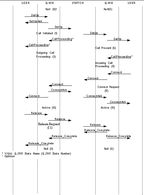
man qcc_bld_connect. FIGURE A-3 illustrates the message flow during typical call setup and tear down.
|
Creates and encodes a message; enables customization of a limited set of values, depending on the message type. Configurable values are passed in as parameters. |
Encoded Q.2931 message (in the format shown in FIGURE A-2) |
||
|
Encoded Q.2931 message (in the format shown in FIGURE A-2) |
|||
|
Returns the maximum length of the buffer that should be allocated for the second strbuf in a Q.2931 message. Only applicable to user space applications; the kernel API allocates the buffers inside the qcc_bld/qcc_pack functions. |
|||
|
Creates a message structure with the required values set. You can further customize the structure using qcc_set_ie. |
|||
|
Updates or inserts values for an information element into a message structure. |
Message structure and IE structure (defined in
|
||
|
Takes a message structure and encodes it into an actual Q.2931 message, consisting of the two mblks (or strbufs) illustrated in FIGURE A-2. |
Encoded Q.2931 message (in the format shown in FIGURE A-2) |
||
|
The reverse of qcc_pack_*: takes an encoded message and decodes the data into a message structure. |
Encoded Q.2931 message (in the format shown in FIGURE A-2) |
To make a call, send a SETUP message down to Q.93B and wait for a SETUP_ACK from Q.93B. The SETUP message should include a Broadband Higher Layer Information (BHLI) information element that contains a four-octet SAP identified as User Specific Information. The SAP is used to identify the application on the receiving host to which the Q.93B should direct the message. After receiving a SETUP_ACK with a 0 error field, wait for either a CALL_PROCEEDING, ALERTING, CONNECT, or RELEASE_COMPLETE message from Q.93B (all other messages are ignored by Q.93B). After you receive the CONNECT message, you can use the virtual channel.
Respond to a SETUP message from Q.93B with either a CALL_PROCEEDING, ALERTING, CONNECT, or RELEASE_COMPLETE message to Q.93B. After yu receive the CONNECT_ACK message, you can use the virtual channel.
To clear an active call or a call in progress, send a RELEASE message down to Q.93B and wait for a RELEASE_COMPLETE from Q.93B. Any time you receive a RELEASE_COMPLETE message from Q.93B, release the virtual channel if the call is active or in progress.
Q.93B never sends a RELEASE message to the end user; it will always send a RELEASE_COMPLETE. Only send the RELEASE_COMPLETE message when rejecting a call in response to a SETUP message from Q.93B. At any other time, to reject or tear down a call, send a RELEASE message to Q.93B.
If for any reason Q.93B cannot process a SETUP message received from an end user, the SETUP_ACK is returned with an error value set, and call setup is not continued. The error value will be one of the cause codes specified in the ATM Forum UNI standard.

Connecting to the ATM device driver involves several steps, some of which include several ioctl calls. To create a more standardized interface for user space applications, a set of atm_util functions is available to application writers. An overview of those functions is provided in . For more detailed information, refer to the atm_util(3) man page. The ba(7) man page contains a more detailed discussion of the driver-supported ioctls.
|
Allocates constant bit rate bandwidth with more granularity than atm_allocate_bw |
||
|
Note - The following discussion uses user space function names. Refer to TABLE A-4 for the corresponding kernel space function or ioctl. |
To establish a data path, the application must first open the ATM driver and attach to a specific physical interface using atm_open() and atm_attach(). Next, the connection is associated with one or more VC(s), using atm_add_vpci(). If a call has been established using Q.2931 signalling, the vpci provided to atm_add_vpci() is the vpci that was included in the Q.2931 signalling messages received while establishing the call.
An encapsulation method must also be selected. The method of encapsulation is selected when the VC is associated with a stream (the atm_add_vpci() call). Currently, null and LLC encapsulation are supported. Null encapsulation implies that a message consists only of data preceded by a four-byte vpci. This type of encapsulation is most commonly used with raw mode. LLC encapsulation implies that an LLC header precedes the data. This header includes the SAP associated with the application's stream (using atm_bind()).
You can also select a mode of operation to determine the format of the message blocks passed to the ATM device driver. DLPI mode is set by default; however, the user can select raw mode with a call to atm_setraw(). DLPI mode implies that two or more mblocks will be sent to the driver. The first, which corresponds to the ctl buffer sent in the putmsg() system call, contains the dlpi message type, which is dl_unitdata_req for transmit and dl_unitdata_ind for receive. The vpci is included in this mblock as well. The dl_unitdata_req and dl_unitdata_ind header formats are defined in the header file <sys/dlpi.h>. The second and subsequent mblocks (corresponding to the data buffer in the putmsg() system call) contain the message.
Raw mode implies that the four-byte vpci is sent in the first mblock (corresponding to the ctl buffer in the putmsg() system call) followed by data. Any subsequent mblocks (the data buffer in the putmsg() system call) contain only data.
Although the encapsulation and operational mode can be chosen independently, typically, DLPI mode is used for LLC-encapsulated traffic and raw mode is used for null encapsulation.
The driver's handling of packets depends on both the encapsulation method and the operational mode. For LLC-encapsulated traffic running in dlpi mode, the driver automatically adds the LLC header on transmit and strips the LLC header on receive before sending the message up the dlpi mode stream. In raw mode, however, the driver does not modify the packets at all. This includes any header included with the packet. Thus, an application using raw mode and LLC encapsulation must include its own headers on transmit and receives data with the LLC header intact.
Received packets are directed to application streams based on the type of encapsulation in use. If a packet is null-encapsulated, it is sent up the stream associated with the vpci on which the packet was received. If a packet is LLC-encapsulated, it is sent to the stream that has bound (using atm_bind()) the SAP found in the LLC header.
Copyright © 2002, Sun Microsystems, Inc. All rights reserved.