| Netra 440 Server Service Manual
|
   
|
This appendix provides reference information about the system back panel ports and pin assignments.
Topics covered in this appendix include:
Serial Port (TTYB)
The serial port connector (TTYB) is a DB-9 connector that can be accessed from the back panel.
FIGURE B-1 Serial Port Pin Numbering

TABLE B-1 Serial Port Connector Signals
|
Pin
|
Signal Description
|
Pin
|
Signal Description
|
|
1
|
Data Carrier Detect
|
6
|
Data Set Ready
|
|
2
|
Receive Data
|
7
|
Request to Send
|
|
3
|
Transmit Data
|
8
|
Clear to Send
|
|
4
|
Data Terminal Ready
|
9
|
Ring Indicate
|
|
5
|
Ground
|
|
|
USB Ports
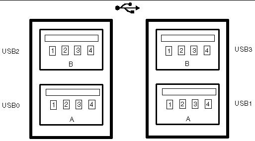
Four Universal Serial Bus (USB) ports are located on the motherboard in a double-stacked layout. The ports can be accessed from the back panel.
FIGURE B-2 USB Connector Pin Numbering

TABLE B-2 USB Ports Pin Numbering
|
Pin
|
Signal Description
|
Pin
|
Signal Description
|
|
A1
|
+5 V (fused)
|
B1
|
+5 V (fused)
|
|
A2
|
USB0/1-
|
B2
|
USB2/3-
|
|
A3
|
USB0/1+
|
B3
|
USB2/3+
|
|
A4
|
Ground
|
B4
|
Ground
|
Ethernet Ports
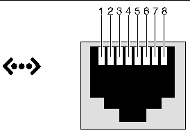
Two RJ-45 Gigabit Ethernet ports (NET0, NET1) are located on the system motherboard and can be accessed from the back panel. The Ethernet interfaces operate at 10 Mbps, 100 Mbps, and 1000 Mbps.
FIGURE B-3 Ethernet Connector Pin Numbering

TABLE B-3 Ethernet Connector Pin Signals
|
Pin
|
Signal Description
|
Pin
|
Signal Description
|
|
1
|
Transmit/Receive Data 0 +
|
5
|
Transmit/Receive Data 2 -
|
|
2
|
Transmit/Receive Data 0 -
|
6
|
Transmit/Receive Data 1 -
|
|
3
|
Transmit/Receive Data 1 +
|
7
|
Transmit/Receive Data 3 +
|
|
4
|
Transmit/Receive Data 2 +
|
8
|
Transmit/Receive Data 3 -
|
Network Management Port
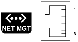
The network management port (labeled NET MGT) is an RJ-45 connector located on the ALOM system controller card and can be accessed from the back panel. This port needs to be configured prior to use.
FIGURE B-4 Network Management Port Pin Numbering

TABLE B-4 Network Management Port Pin Signals
|
Pin
|
Signal Description
|
Pin
|
Signal Description
|
|
1
|
Transmit Data +
|
5
|
Common Mode Termination
|
|
2
|
Transmit Data -
|
6
|
Receive Data -
|
|
3
|
Receive Data +
|
7
|
Common Mode Termination
|
|
4
|
Common Mode Termination
|
8
|
Common Mode Termination
|
Serial Management Port (SERIAL MGT)
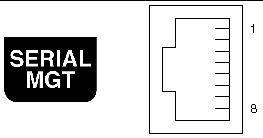
The serial management port (labeled SERIAL MGT) is an RJ-45 connector located on the ALOM system controller card and can be accessed from the back panel. This port is the default connection to the system. This is also the TTYA port for the system.
FIGURE B-5 Serial Management Port Pin Numbering

TABLE B-5 Serial Management Port Pin Signals
|
Pin
|
Signal Description
|
Pin
|
Signal Description
|
|
1
|
Request to Send
|
5
|
Ground
|
|
2
|
Data Terminal Ready
|
6
|
Receive Data
|
|
3
|
Transmit Data
|
7
|
Data Set Ready
|
|
4
|
Ground
|
8
|
Clear to Send
|
SCSI Port
The SCSI serial data connector is located on the motherboard and can be accessed from the back panel.
FIGURE B-6 SCSI Port Pin Numbering

TABLE B-6 SCSI Port Pin Signals
|
Pin
|
Signal Description
|
Pin
|
Signal Description
|
|
1
|
Data12 +
|
35
|
Data12 -
|
|
2
|
Data13 +
|
36
|
Data13 -
|
|
3
|
Data14 +
|
37
|
Data14 -
|
|
4
|
Data15 +
|
38
|
Data15 -
|
|
5
|
Parity1 +
|
39
|
Parity1 -
|
|
6
|
Data0 +
|
40
|
Data0 -
|
|
7
|
Data1 +
|
41
|
Data1 -
|
|
8
|
Data2 +
|
42
|
Data2 -
|
|
9
|
Data3 +
|
43
|
Data3 -
|
|
10
|
Data4 +
|
44
|
Data4 -
|
|
11
|
Data5 +
|
45
|
Data5 -
|
|
12
|
Data6 +
|
46
|
Data6 -
|
|
13
|
Data7 +
|
47
|
Data7 -
|
|
14
|
Parity0 +
|
48
|
Parity0 -
|
|
15
|
Ground
|
49
|
Ground
|
|
16
|
DIFF_SENSE
|
50
|
Ground
|
|
17
|
TERM_PWR
|
51
|
TERM_PWR
|
|
18
|
TERM_PWR
|
52
|
TERM_PWR
|
|
19
|
(N/C)
|
53
|
(N/C)
|
|
20
|
Ground
|
54
|
Ground
|
|
21
|
ATN +
|
55
|
ATN -
|
|
22
|
Ground
|
56
|
Ground
|
|
23
|
BSY +
|
57
|
BSY -
|
|
24
|
ACK +
|
58
|
ACK -
|
|
25
|
RST +
|
59
|
RST -
|
|
26
|
MSG +
|
60
|
MSG -
|
|
27
|
SEL +
|
61
|
SEL -
|
|
28
|
CD +
|
62
|
CD -
|
|
29
|
REQ +
|
63
|
REQ -
|
|
30
|
I/O +
|
64
|
I/O -
|
|
31
|
Data8 +
|
65
|
Data8 -
|
|
32
|
Data9 +
|
66
|
Data9 -
|
|
33
|
Data10 +
|
67
|
Data10 -
|
|
34
|
Data11 +
|
68
|
Data11 -
|
Alarm Port
The alarm port uses a standard DB-15 connector. In a telecommunications environment, use this port to connect to the central office alarming system. FIGURE B-7 shows the pin numbering of the alarm port, TABLE B-7 and describes the pin signals.
FIGURE B-7 Alarm Port

TABLE B-7 Alarm Port Signals
|
Pin
|
Signal Description
|
Pin
|
Signal Description
|
|
1
|
RESERVED
|
9
|
ALARM1_NC
|
|
2
|
RESERVED
|
10
|
ALARM1_COM
|
|
3
|
NC
|
11
|
ALARM2_NO
|
|
4
|
NC
|
12
|
ALARM2_NC
|
|
5
|
ALARM0_NC
|
13
|
ALARM2_COM
|
|
6
|
ALARM0_NO1
|
14
|
ALARM3_NO
|
|
7
|
ALARM0_COM1
|
15
|
ALARM3_COM
|
|
8
|
ALARM1_NO
|
CHASSIS
|
FRAME GND
|


 When the system is in Standby mode.
 When the server is powered on and the operating system has not booted or has failed.