| Sun Fire V60x Compute Grid Rack System Installation Guide |
| Sun Fire V60x Compute Grid Rack System Installation Guide |
| C H A P T E R 2 |
|
Sun Fire V60x Compute Grid Rack System Software Overview and Installation |
The Sun Fire V60x Compute Grid rack system is shipped with operating system and grid management software preinstalled to the Cluster Grid Manager (CGM) node. The grid master node and compute nodes are not shipped with preinstalled software.
This chapter contains overview information and procedures for performing an initial setup and basic configuration of the system software components. The procedure for deploying the operating system to the grid master node and grid compute nodes is also included.
The information in this chapter is organized into the following sections.
The following diagram represents the software components that are preinstalled on the CGM node and how they are related. The sections that follow give brief descriptions of the components that are labeled in the diagram.
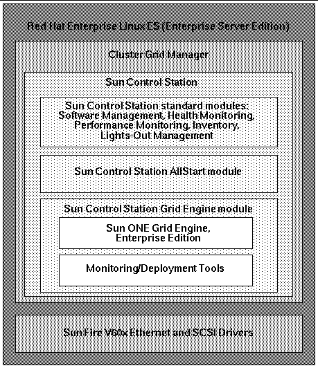
Red Hat Enterprise Linux (Enterprise Server Edition) is the Linux operating system that is preinstalled on the CGM node of the system.
For detailed information about administering and customizing Linux operating system software, refer to the manual that was shipped with your Red Hat Enterprise Linux 2.1 media kit.
As shown in FIGURE 2-1, the Cluster Grid Manager software is comprised of several components that supplement each other to enable you to install, set up, and monitor activities on your Sun Fire V60x Compute Grid.
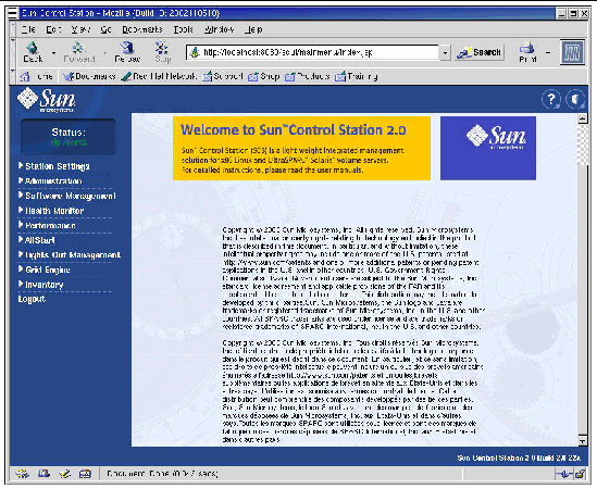
Sun Control Station and its standard control modules, plus the AllStart module and the Grid Engine module, comprise the Cluster Grid Manager interface that you use to administer your Sun Fire V60x Compute Grid. See FIGURE 2-2 for a sample Cluster Grid Manager main window.
You access the Cluster Grid manager main window by using a browser to go to the IP address of your CGM node (for example, http:\\n.n.n.n, where n.n.n.n is the IP address of your CGM node). Instructions for setting up the CGM node so that it can be correctly accessed are described in Logging In and Setting Up the System Identity.
Documentation for the Cluster Grid manager software components can be accessed with the Help button, which is the button with the question mark (?), in the upper-right corner (see FIGURE 2-2).
Sun Control Station (SCS) is a server management and monitoring tool. Software control modules that are included with your system are easily accessed and controlled through the Cluster Grid Manager main window.
There is both a server-side component and a client-side component for SCS.
The standard control modules that are shipped with Sun Control Station are listed and described briefly here. All modules are accessed from the left-side panel in the Cluster Grid Manager main window (see an example in FIGURE 2-2).
For detailed information about SCS software and the standard control modules that are integrated with it, refer to the Sun Control Station Administration Manual, (817-3603). This manual and those for the control modules are accessed by clicking the Help button on the Cluster Grid Manager main window.
This module enables you to manage software package files on your system. For example, you can view, download, and upload package files, view lists of required package files, and install and publish package files. See Sun Control Station Software Management Module (817-3611), which you can access with the Cluster Grid Manager Help button.
This module enables you to monitor the health status of your managed hosts according to parameters that you define. You can retrieve and view health-status data, verify network communication, and configure the parameters for health monitoring, including email alerts for critical system events. See Sun Control Station Health Monitoring Module (817-3607), which you can access with the Cluster Grid Manager Help button.
This module enables you to view the performance of your managed hosts according to various parameters. You can view and update performance data for a host or group of hosts. See Sun Control Station Performance Monitoring Module (817-3610), which you can access with the Cluster Grid Manager Help button.
This module enables you to keep track of the hardware components in your system. You can view and update a summary inventory of the hardware components in a host or group of hosts. See Sun Control Station Inventory Module (817-3608), which you can access with the Cluster Grid Manager Help button.
This module enables you to remotely perform certain management functions. For example, this module enables you to remotely power on and power off a host, perform a hardware reset, illuminate an LED for host identification, and view sensor data and the system event log. See Sun Control Station Lights-Out Management Module (817-3609), which you can access with the Cluster Grid Manager Help button.
|
Note - Refer to the Sun Fire V60x Compute Grid Rack System Release Notes for a list of supported browsers and Java |
The AllStart module facilitates the installation of operating system software to the system nodes. This module integrates the KickStart utility of Linux. You can access the AllStart module through the Cluster Grid Manager main window.
See Sun Control Station AllStart Module (817-3605), which you can access with the Cluster Grid Manager Help button.
The AllStart control module provides a common user interface for creating operating system software payloads, defining client profiles, and deploying the software payloads to the clients.
The Grid Engine module is integrated with Sun ONE Grid Engine, Enterprise Edition (S1GEEE) software. The Grid Engine module deploys the S1GEEE software to the grid master node, which you can designate as the S1GEEE master host, and to the grid compute nodes, which you can designate as S1GEEE execution hosts.
You can access the Grid Engine module and its functions through the Cluster Grid Manager main window. For basic instructions on using the Grid Engine module, refer to Configuring the Grid Engine Module. For more detailed information about the Grid Engine module, you can access the document, Sun Control Station Grid Engine Module (817-3606) with the Cluster Grid Manager Help button.
S1GEEE documentation can also be accessed with the Cluster Grid Manager Help button.
The procedures in this section describe how to get the system software up and running during initial installation and login. For detailed information about customizing and administering your system after your installation, references to software documentation are provided.
TABLE 2-1 shows the information that you will need to obtain from your site's system administrator to complete the software setup for your system. Default settings are listed if they exist. The right-hand column is supplied for you to write down the settings that you will use for your site.
|
Note - Begin this procedure after you have powered on the system as described in Powering On the System. |
1. Slide the KVM unit out from the rack until the video screen can be opened.
The KVM is precabled directly to the CGM node. You should see the Red Hat Linux login display on the video screen.
2. Log in as root user at the Red Hat Linux login screen, using the default entries shown below.
3. Open a terminal window and change the default Linux root password to a password of your choosing.
Use the passwd command to change the root password on the system.
4. Configure an IP address for the system's terminal server as follows:
a. Make a Telnet connection to the default IP address of the terminal server in your first rack.
The default IP address of the terminal server is 192.168.160.10. The system has been preconfigured so that no changes to routing tables are required.
telnet 192.168.160.10
Login: InReach
Password: access
b. At the InReach prompt, enter the enable command.
c. Enter the following password when you are prompted.
d. When the InReach prompt appears again, enter the config command.
e. At the prompts, enter the following commands to configure the terminal server IP address.
Config:0>> interface 1
Intf1-1:0>> address n.n.n.n
Where n.n.n.n is an IP address compatible with your local network.
You can safely ignore the message, Warning, interface active, which appears because you are about to change the interface.
f. At the prompts, enter the following commands to configure the terminal server netmask setting.
Intf1-1:0>> mask n.n.n.n
Intf1-1:0>> exit
Where n.n.n.n represents a netmask setting that is compatible with your local network.
g. At the prompts, enter the following commands to configure the terminal server gateway setting.
Config:0>> gateway n.n.n.n
Config:0>> exit
Where n.n.n.n represents a gateway setting that is compatible with your local network. It might take several seconds for the gateway setting to take effect.
h. When the InReach prompt appears, save the changes with the following command.
InReach:0>> save configuration flash
i. At the InReach prompts, enter the exit command twice to return to the system's root prompt.
InReach:0>> exit
InReach:0> exit
5. Configure an IP address for the CGM node as follows.
a. Change to the network-scripts directory.
# cd /etc/sysconfig/network-scripts/
b. Delete the ifcfg-eth0 file.
You can confirm the deletion by typing Y when prompted.
c. Edit the ifcfg-eth1 file to read as follows, substituting your IP address, netmask, and gateway information.
DEVICE=eth1
ONBOOT=yes
BOOTPROTO=static
IPADDR=n.n.n.n
NETMASK=n.n.n.n
GATEWAY=n.n.n.n
Where n.n.n.n represents the respective settings that are compatible with your local network. Use vi or another file-editing tool, such as Gedit, which is supplied with your Gnome desktop (start Gedit by typing gedit at a command line).
d. At the command line, use the following command to apply your changes.
6. Verify that the IP addresses for the terminal server and CGM node are set correctly by pinging the address of the terminal server from the CGM node:
Where n.n.n.n represents the IP address of the terminal server.
7. After you have verified that the CGM node is visible on your network, start a browser and type the following URL.
Where n.n.n.n is the IP address that you assigned to the CGM node.
Refer to The Sun Fire V60x Compute Grid Rack System Release Notes for a list of supported browsers and Java plug-ins for viewing SCS software.
8. Read the Sun Control Station license agreement that appears and accept the license agreement if you agree with the terms.
A Sun Control Station Welcome page appears.
9. Go to the Sun Control Station login page for your CGM node by entering the URL in the format that is shown on the Welcome page:
Where n.n.n.n is the IP address that you assigned to the CGM node.
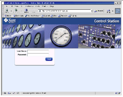
10. At the Sun Control Station login page (see FIGURE 2-3), log in as the SCS administrator using the default entries shown below, then click the Login button.
User Name: admin
Password: admin
11. After the SCS main window opens (see FIGURE 2-2), change the default SCS admin password to a password of your choosing, as follows:
a. In the left-side panel, click on Station Settings > Password.
b. Enter the new password in the supplied fields, then click the Save button.
The message, "Password changed successfully," appears when the change is complete.
The AllStart module deploys the software to the Sun Fire V60x clients. The following procedure provides a quick path through AllStart to accomplish this specific software deployment. For a complete description of the module, and instructions for using AllStart, refer to Sun Control Station 2.0 AllStart Module (817-3605) documentation provided with the AllStart module.
Using the AllStart module to load software to system nodes consists of the following actions:
1. Creating the AllStart distributions. See Creating AllStart Distributions.
2. Creating a payload(s) from files and distributions. See Creating AllStart Payloads.
3. Creating a profile(s) containing configuration information. See Creating AllStart Profiles.
4. Creating and enabling clients to which you will load the payload. See Creating and Enabling Clients.
5. Defining network service settings for the network that your system is on. See Defining Network Service Settings.
6. Powering on or rebooting client nodes so that they network-boot and pull the payload from the Sun Control Station. See Deploying Software Payloads to Compute Nodes.
The following sections walk you through each of these steps.
You must first define the software distributions that you will later load to the compute nodes.
1. In the Cluster Grid Manager main window, select AllStart > Distributions from the left-side panel.
The AllStart Distributions window appears on the right side of the screen.
2. Click on Add at the bottom of the AllStart Distributions window.
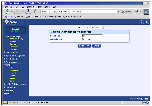
The Upload Distribution From CDROM window appears on the right side of the screen.
3. In the Upload Distribution From CDROM window, fill in the fields to create a unique description for the distribution. See FIGURE 2-4 for an example.
The CDROM Device field should contain /dev/cdrom as the default entry.
4. Insert the Linux CD 1 into the CGM node, then click Upload Now.
A progress bar indicates the progress of the upload. If a file manager window opens when you insert the CD, you can close the file manager.
5. After the progress bar indicates that progress is 100%, click Done and remove the Linux CD 1 from the CGM node.
You are prompted to insert the next CD.
6. Insert the next CD in your Linux distribution, then click Continue.
7. Continue loading CDs when prompted until you have loaded the last CD in your Linux distribution, then click Done.
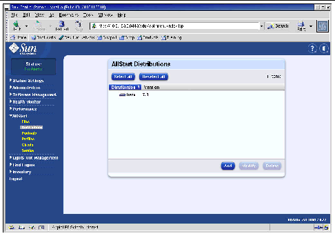
When uploading is complete, the distribution that you created appears in the list in the AllStart Distributions window. See FIGURE 2-5 for an example.
8. Continue with Creating AllStart Payloads.
After the required distributions are available, use AllStart to create payloads that will be deployed to the compute nodes.
1. In the Cluster Grid Manager main window, select AllStart > Payloads in the left-side panel.
The AllStart Payloads window appears on the right side of the screen.
2. In the AllStart Payloads window, click Add.
The Create AllStart Payload window appears on the right side of the screen. See FIGURE 2-6 for an example.
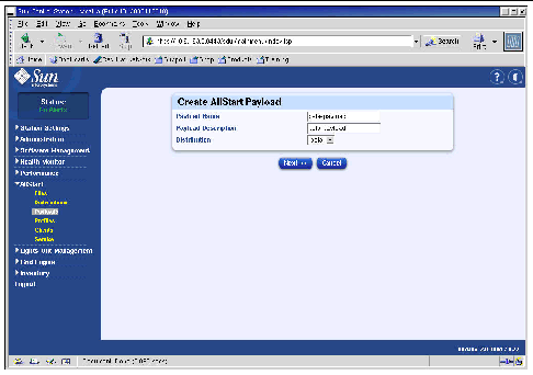
3. In the Create AllStart Payload window, create the payload by filling in the fields and selecting the Linux distribution that you created.
4. When you are finished, click Next.
The AllStart Payload Distribution Specific Options window appears on the right side of the screen. See FIGURE 2-7 for an example.
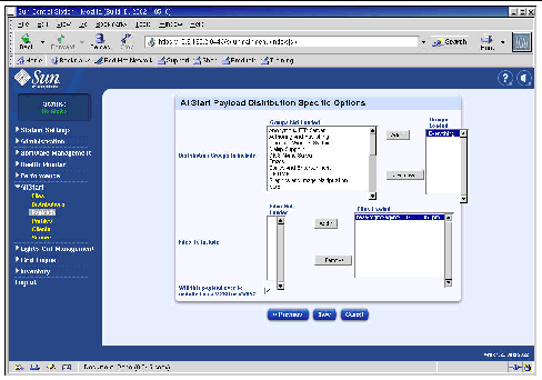
5. In the Distribution Groups To Include list, select the groups that you require for the applications that you will use and move them to the Groups Loaded column.
You can select all groups by selecting the "Everything" option and moving it to the Groups Loaded column.
6. In the Files to Include list, verify that the Files Loaded selection list includes the
base-mgmt-agent RPM file.
If this file is not included, select it from the Files Not Loaded column and move it to the Files Loaded column.
7. Verify that the check-box for Sun Fire V60x/V65x server installation is selected.
This selection ensures that the required drivers for the Sun Fire V60x server are included.
8. When you are finished, click Save.
The payload is created, with the name you gave it.
9. Wait until the progress bar indicates 100%, then click Done.
When payload creation is complete, the payload that you created appears in the list in the AllStart Payloads window. See FIGURE 2-8 for an example.

10. Continue with Creating AllStart Profiles.
After the payloads have been defined, use AllStart to create installation profiles for the compute nodes.
1. From the left-hand menu click on AllStart > Profiles.
The AllStart Profiles window appears.
2. Click on Add at the bottom of the AllStart Profiles window.
The Add AllStart Profile window appears on the right side of the screen.
3. Create the AllStart profile by defining the options in the series of windows that appear.
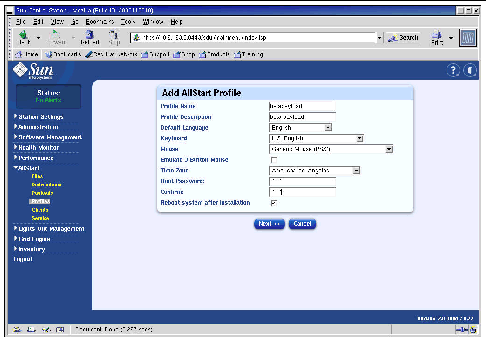
a. In the Add AllStart Profile window, select the settings that are appropriate for your site (see FIGURE 2-9 for an example). Click Next when you are finished.
|
Note - If you use the KVM unit that is provided with the system, you must select "U.S. English" as the Keyboard type. |
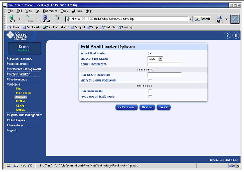
b. In the Edit Boot Loader Options window, verify that the following required entries are selected (see FIGURE 2-10 for an example). Click Next when you are finished.
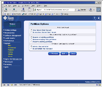
c. In the Partition Options window, verify that the following required options are selected (see FIGURE 2-11 for an example). Click Next when you are finished.
d. Use the Disk Partition Information window to create the partitions you require on the client node that you are installing to, as follows:
i. In the Disk Partition Information window, click Add.
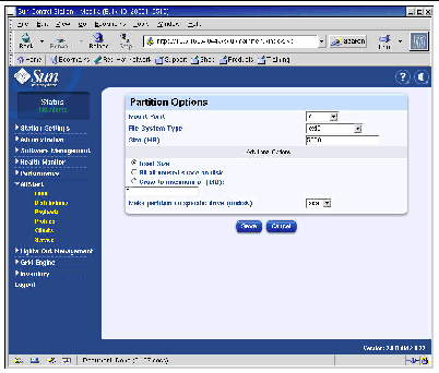
The Partition Options window appears, where you define the parameters for one disk partition.
ii. Create your first disk partition by defining the partition parameters, then click Save when you are done. See FIGURE 2-12 for an example.
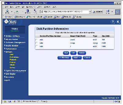
After you click save, you are returned to the Disk partition Information window, where the partition you created appears in the list (see FIGURE 2-13).
iii. To create another partition, click Add again in the Disk Partition Information window and define another partition as in Step ii.
Three different example partition configurations are listed as follows:
iv. After you have created all your partitions, click Next on the Disk Partition Information window.
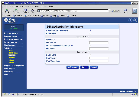
e. In the Edit Authentication Information window, verify that the following required options are selected (see FIGURE 2-14 for an example). Click Next when you are finished.
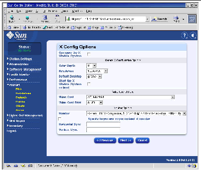
f. In the X Config Options window, make the selection that you require (see FIGURE 2-15 for an example). Click Next when you are finished.
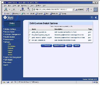
g. In the Edit Custom Script Options window, verify that the following required options are selected (see FIGURE 2-16 for an example). Click Save when you are finished.
These scripts enable serial redirection.
4. Wait until the progress bar indicates 100%, then click Done.
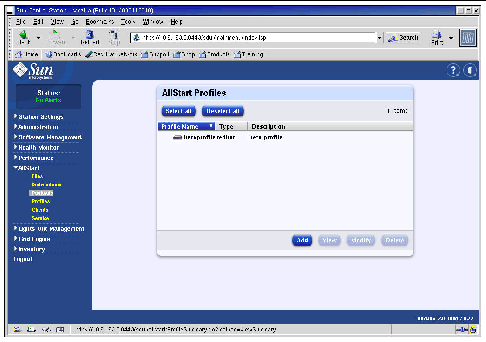
When profile creation is complete, the profile that you created appears in the list in the AllStart Profiles window. See FIGURE 2-17 for an example.
5. Continue with Creating and Enabling Clients.
After the installation profiles have been defined, use AllStart to create and enable clients to which the payload will be deployed.
1. From the left-hand menu click AllStart > Clients.
The AllStart Clients window opens.
2. Click on Add at the bottom of the window.
The Create AllStart Client window appears in the right side of the screen.
3. In the Create AllStart Client window, create the client by defining the information for the node to which you will be loading the payload (see FIGURE 2-18 for an example). Verify that the following required options are selected:
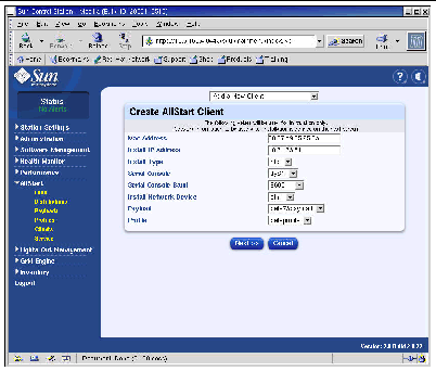
4. When you are finished defining the Client options, click Next.
The Network Interfaces window appears.
5. In the Network Interfaces window, click Add.
The Enter Network Interface Information window appears.
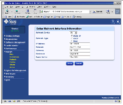
6. In the Enter Network Interface Information window, create the network interface by defining the information for the node to which you will be loading the payload (see FIGURE 2-19 for an example).
Verify that the following required options are selected:
|
Note - When you enter a host name, use the short host name format, not the full host name format that would include the domain name. |
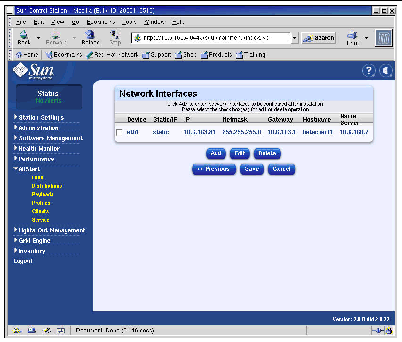
7. When you are finished defining the network interface, click Save.
You are returned to the Network Interfaces window. The network interface that you created is listed (see FIGURE 2-20 for an example).
8. In the Network Interfaces window, click Save.
A progress bar indicates the progress of the network interface creation.
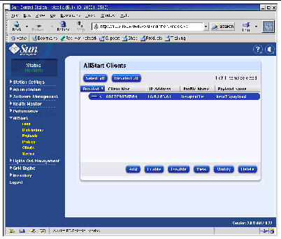
9. When the progress bar indicates 100%, click Done.
You are returned to the AllStart Clients page. The client that you created is listed (see FIGURE 2-21 for an example).
10. In the AllStart Clients window, select the clients that you want to enable, then click Enable.
A progress bar indicates the progress of the client enabling.
11. When the progress bar indicates 100%, click Done.
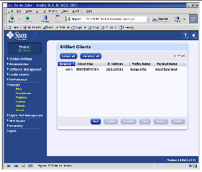
The client entry is enabled so that it is visible to that node in the system. Enabled clients are indicated by a Y character under the Enabled heading on the AllStart Clients window. See FIGURE 2-22 for an example.
12. Repeat Step 3 through Step 11 for all nodes in your system.
13. Continue with Defining Network Service Settings.
1. In the Cluster Grid Manager main window, select AllStart > Service from the left-side panel.
The AllStart Current Service Settings window appears on the right side of the screen.
The Modify Service Settings window appears.
3. In the Modify Service Settings window, make the following required settings (see FIGURE 2-23 for an example):
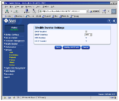
4. When you are finished with the settings, click Save.
A progress bar indicates the progress of the service setting.
5. When the progress bar indicates 100%, click Done.
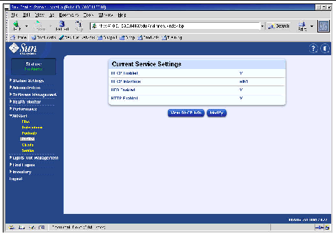
The settings that you made are shown in the AllStart Current Service Settings window (see for an example).
6. Continue with Deploying Software Payloads to Compute Nodes.
After you have created clients to which you will deploy payloads, you start the deployment by powering on or resetting the client nodes.
1. In a terminal window, telnet to the terminal server IP address and port that corresponds to the node to which you are deploying software.
Where n.n.n.n is the IP address of the terminal server and xx is the two-digit number that corresponds to the number of the node to which you are deploying software (see the following note).
2. Power on or reset the client node to start the deployment of the payload that was selected in the client profile.
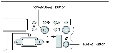
a. Press the Reset button on the node (see FIGURE 2-25).
b. When a prompt appears with the option to press F2 to enter setup, press Escape to initiate a network boot.
c. When you are prompted to select the boot device, select
IBA 1.1.08 slot 0338 and press Return.
The client node pulls the payload from the CGM node.
3. Wait until the deployment progress indicator messages are finished and the terminal window returns to a login prompt.
4. When you are finished downloading the payload to the client node, reboot the client node (if it does not reboot automatically).
Repeat this procedure for each client node to which you are deploying software.
Use the following procedure to define the compute nodes of your system as SCS managed hosts.
|
Note - You cannot add the CGM node as an SCS managed host because it is the dedicated management node of the system, from which SCS managed hosts are managed. |
1. In the Cluster Grid Manager main window, select Administration > Hosts from the left-side panel.
The Managed Hosts window appears on the right side of the screen.
2. In the Managed Hosts window, click Add.
3. In the Add Host window, define the settings for the node that you are defining as an SCS managed host. See FIGURE 2-26 for an example.
4. Verify that the Install All Possible Modules box is selected.
This ensures that all of the SCS agents are installed on the newly managed host.
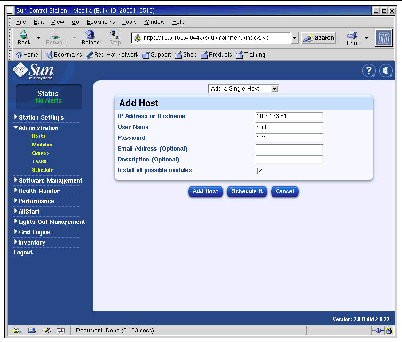
5. When you are finished with the settings, click Add Host.
A progress bar indicates the progress of the managed host addition.
6. When the progress bar indicates 100%, click Done.
You are returned to the Managed Hosts window. The managed host you added is listed (see FIGURE 2-27 for an example).
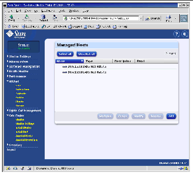
7. Repeat this procedure for all compute nodes in your system.
The Compute Grid software module provides the following main functions.
 ONE Grid Engine, Enterprise Edition (S1GEEE)
|
Note - Before you can manage the compute nodes of your system with S1GEEE software, you must add the nodes as SCS managed hosts. See Adding Compute Nodes as SCS Managed Hosts. |
The Grid Engine module automatically deploys S1GEEE to any number of selected nodes on the compute grid. It deploys the S1GEEE master host onto a grid master node of your choosing (see Grid Master Node), and then deploys S1GEEE execution hosts onto specified compute nodes (see Compute Nodes). You can also choose to uninstall an execution host at a later time, or uninstall all hosts, including the master host. You can then later reinstall a host on any systems.
To use the Grid Engine module to deploy a S1GEEE master host (grid master node), perform the following steps.
1. In the Cluster Grid Manager main window, click on the Grid Engine menu item in the left-hand menu.
A drop-down menu of choices for the Grid Engine module appears.
If this is an initial installation, a license agreement appears.
3. Read any license agreement that appears and accept it if you agree with the terms.
|
Note - You are instructed on-screen to click on Install Master again after accepting the license agreement. |
The Install Sun ONE Grid Engine Master window appears.
4. In the Install Sun ONE Grid Engine Master window, select one node from the list of managed hosts to act as the S1GEEE master host (grid master node). See FIGURE 2-28 for an example.
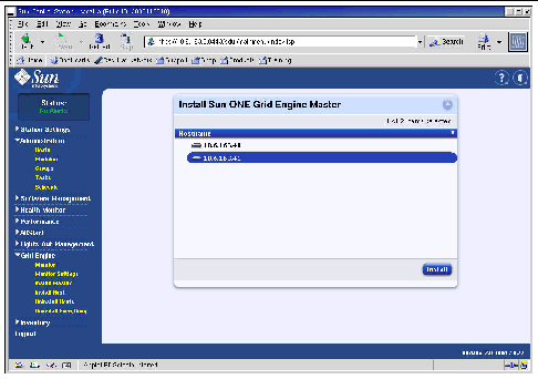
A progress bar indicates the progress of the S1GEEE software deployment to the node.
6. When the progress bar indicates 100%, click Done.
The browser is directed to the Install Sun ONE Grid Engine Compute Hosts window.
To use the Grid Engine module to define S1GEEE compute hosts (compute nodes), perform the following steps.
1. In the Cluster Grid Manager main window, click on the Grid Engine menu item in the left-hand menu.
A drop-down menu of choices for the Grid Engine module appears.
The Install Sun ONE Grid Engine Compute Hosts window appears.
3. Select the nodes that you want to include in the S1GEEE grid.
Unless you want to dedicate a system for non-grid tasks, select all systems by clicking Select All. See FIGURE 2-29 for an example.
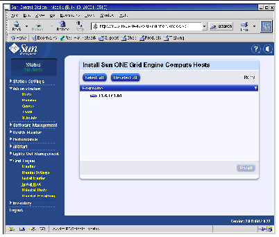
The S1GEEE software is deployed to each selected node in sequence and a progress bar indicates the progress of the software deployment.
5. When the progress bar indicates 100%, click Done.
When you are finished with installing, your browser is redirected to the Grid Engine Monitor page (see Monitoring Compute Grid Tasks).
If, at a later point, you wish to add more nodes to the S1GEEE grid, you can return to the Install Compute Hosts page by clicking on the Grid Engine > Install Compute Hosts menu item in the left-side panel.
When you are finished with installation procedure, your browser is redirected to the Monitor page. From this page, you can view various S1GEEE statistics on your Sun Fire V60x Compute Grid. These include:
The Monitor page is automatically refreshed every two minutes. The information on the page is drawn from a database that is updated every two minutes. For every statistic, a time stamp is given to indicate when the statistic was last updated.
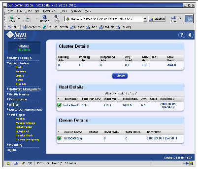
You can always return to the Monitor page by clicking the Grid Engine > Monitor menu item in the left-side panel. See FIGURE 2-2 for a sample Monitor window.
You can uninstall Sun ONE Grid Engine software, either from individual S1GEEE execution hosts, or from all hosts in the S1GEEE grid, including the S1GEEE master host.
|
Note - You cannot uninstall only the S1GEEE master host, since it is not possible to operate S1GEEE execution hosts without an S1GEEE master host. |
After you have uninstalled an S1GEEE execution host, Sun Fire V60x Compute Grid tasks are no longer sent to that node for execution. However, the other installed modules, such as Inventory, Health, and Performance, continue to operate as before. Any other software that has been installed on that system should also continue to operate normally.
1. In the Cluster Grid Manager main window, click on the Grid Engine module menu item in the left-hand menu.
A drop-down menu of choices for the Grid Engine module appears.
3. Select one or more nodes from which to uninstall S1GEEE software.
4. Ensure that no jobs are running on the systems to be uninstalled.
Refer to Sun Grid Engine, Enterprise Edition 5.3 Administration and User's Guide (816-4739) for instructions on managing queues.
The S1GEEE software is shutdown and removed from the selected systems, and the S1GEEE master host is instructed to remove those execution hosts from the S1GEEE system.
1. In the Cluster Grid Manager main window, click on the Grid Engine module menu item in the left-hand menu.
A drop-down menu of choices for the Grid Engine module appears.
2. Click on Uninstall Everything.
|
Note - Do not go to the next step until you are certain that you want to terminate all running jobs and remove all record of previous jobs. |
This immediately terminates all running jobs, removes all S1GEEE software from all nodes in the S1GEEE, and removes all record of previously run jobs and all record of S1GEEE utilization.
| Sun Fire V60x Compute Grid Rack System Installation Guide | 817-3072-10 |
Copyright © 2003, Sun Microsystems, Inc. All rights reserved.