| C H A P T E R 10 |
|
Troubleshooting |
This chapter provides troubleshooting information for a system administrator. The chapter describes the following topics:
The physical address represents a physical characteristic that is unique to the device. Examples of physical addresses include the bus address and the slot number. The slot number indicates where the device is installed.
You reference a physical device by the node identifier--agent ID (AID). The AID ranges from 0 to 31 in decimal notation (0 to 1f in hexadecimal). In the device path beginning with ssm@0,0 the first number, 0, is the node ID.
CPU/Memory board and memory agent IDs (AIDs) range from 0 to 23 in decimal notation (0 to 17 in hexadecimal). The system can have up to three CPU/Memory boards.
Each CPU/Memory board has four CPUs, depending on your configuration. Each CPU/Memory board has up to four banks of memory. Each bank of memory is controlled by one memory management unit (MMU), which is the CPU. The following code example shows a device tree entry for a CPU and its associated memory:
There are up to four CPUs on each CPU/Memory board (TABLE 10-1):
|
The first number in the columns of agent IDs is a decimal number. The number or letter in parentheses is in hexadecimal notation. |
||||
|---|---|---|---|---|
TABLE 10-2 lists the types of I/O assembly, the number of slots each I/O assembly has, and the systems the I/O assembly types are supported on.
TABLE 10-3 lists the number of I/O assemblies per system and the I/O assembly name.
Each I/O assembly hosts two I/O controllers:
When mapping the I/O device tree entry to a physical component in the system, you must consider up to five nodes in the device tree:
TABLE 10-4 lists the AIDs for the two I/O controllers in each I/O assembly.
|
The first number in the column is a decimal number. The number (or a number and letter combination) in parentheses is in hexadecimal notation. |
|||
|---|---|---|---|
The I/O controller has two bus sides: A and B.
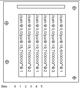
The board slots located in the I/O assembly are referenced by the device number.
This section describes the PCI I/O assembly slot assignments and provides an example of the device path.
The following code example gives a breakdown of a device tree entry for a SCSI disk:
isptwo is the SCSI host adapter
This section describes the PCI I/O assembly slot assignments and provides an example of the device path.
TABLE 10-5 lists, in hexadecimal notation, the slot number, I/O assembly name, device path of each I/O assembly, the I/O controller number, and the bus.
w = onboard LSI1010R SCSI controller
x = onboard CMD646U2 EIDE controller
y = onboard Gigaswift Ethernet controller 0
z = onboard Gigaswift Ethernet controller 1
and * is dependent upon the type of PCI card installed in the slot.

where * is dependent upon the type of PCI card installed in the slot.
These would generate device paths as follows:
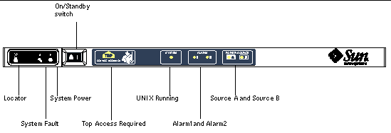
A system fault is any condition that is considered to be unacceptable for normal system operation. When the system has a fault, the Fault LED (


The indicator states are shown in TABLE 10-6. You must take immediate action to eliminate a system fault.
|
Fault indicator lit when fault detected[1] |
||||
|---|---|---|---|---|
|
All power supply indicators are lit by the power supply hardware. There is also a predicted fault indicator. Power supply EEPROM errors do not cause degraded state as there is no indicator control. |
||||
The following topics describe the field replaceable units, by system.
The following FRUs are considered to be ones on which you can deal with faults:
If a fault is indicated on any other FRU or a physical replacement of blacklisted FRUs above is required, then Sun Service should be called.
The following FRUs are considered to be ones on which you can deal with faults:
If a fault is indicated on any other FRU or a physical replacement of blacklisted FRUs above is required, then Sun Service should be called.
The following FRUs are considered to be ones on which you can deal with faults:
|
Note - Only suitably trained personnel or Sun Service are permitted to enter the Restricted Access Location to hot-swap PSUs or hard disk drives. |
If a fault is indicated on any other FRU or a physical replacement of blacklisted FRUs above is required, then Sun Service should be called.
The SC supports the blacklisting feature, which allows you to disable components on a board (TABLE 10-7).
Blacklisting provides a list of system board components that will not be tested and will not be configured into the Solaris Operating System. The blacklist is stored in nonvolatile memory.
Blacklist a component or device if you believe it might be failing intermittently or is failing. Troubleshoot a device you believe is having problems.
There are two system controller commands for blacklisting:
The setls command updates only the blacklist. It does not directly affect the state of the currently configured system boards.
The updated lists take effect when you do one the following:
In order to use setls on the Repeater boards (RP0/RP2), the system first has to be shut down to Standby using the poweroff command.
When the setls command is issued for a Repeater board (RP0/RP2), the SC will be automatically reset to make use of the new settings.
If a replacement Repeater board is inserted, it is necessary to manually reset the SC using the resetsc command. See the Sun Fire Entry-Level Midrange System Controller Command Reference Manual for a description of this command.
In the unlikely event that a CPU/Memory board fails the interconnect test during POST, a message similar to the following appears in POST output:
A CPU/Memory board failing the interconnect test might prevent the poweron command from completely powering on the system. The system then drops back to the lom> prompt.
As a provisional measure, before service intervention is obtained, the faulty CPU/Memory board can be isolated from the system using the following sequence of commands at the SC lom> prompt:
A subsequent poweron command should now be successful.
If you cannot log into the Solaris Operating System, and typing the break command from the LOM shell did not force control of the system back to the OpenBoot PROM ok prompt, then the system has stopped responding.
In some circumstances the host watchdog detects that the Solaris Operating System has stopped responding and automatically resets the system.
Assuming that the host watchdog has not been disabled (using the setupsc command), then the Host Watchdog causes an automatic reset of the system.
Also, you can issue the reset command (default option is -x which causes an XIR to be sent to the processors) from the lom> prompt. The reset command causes the Solaris Operating System to be terminated.
|
1. Complete the steps in Assisting Sun Service Personnel in Determining Causes of Failure.
See Chapter 3.
3. Type the reset command to force control of the system back to the OpenBoot PROM.
The reset command sends an externally initiated reset (XIR) to the system and collects data for debugging the hardware.
4. This step depends on the setting of the Open Boot PROM
error-reset-recovery configuration variable.
5. If the previous actions fail to reboot the system, use the poweroff and poweron commands to power cycle the system.
To power off the system, type:
You might decide that the simplest way to restore service is to use a complete replacement system. In order to facilitate the rapid transfer of system identity and critical settings from one system to its replacement, the System Configuration Card (SCC) can be physically removed from the SCC Reader (SCCR) of the faulty system and inserted into the SCCR of the replacement system.
The following information is stored on the System Configuration Card (SCC):
One indication of problems might be overtemperature of one or more components. Use the showenvironment command to list current status.
Each power supply unit (PSU) has its own LEDs as follows:
In addition there are two system LEDs labelled SourceA and SourceB. These show the state of the power feeds to the system. There are four physical power feeds and they are split into A and B.
Feed A supplies PS0 and PS1, feed B supplies PS2 and PS3. If either PS0 or PS1 receives input power then the SourceA indicator is lit. If either PS2 or PS3 receives input power then the SourceB indicator is lit. If neither of the supplies receives input power, the indicator is turned off.
These indicators are set on the basis of periodic monitoring at least once every 10 seconds.
For information on displaying diagnostic information, see the Sun Hardware Platform Guide, which is available with your Solaris Operating System release.
Provide the following information to Sun service personnel so that they can help you determine the causes of your failure:
Copyright © 2004, Sun Microsystems, Inc. All Rights Reserved.