|
Sun SNMP Management Agent Addendum for the Netra 440 Server |
This document describes how the Netra 440 server fans, power supplies, and LED indicators are represented in the Sun
 Simple Network Management Protocol (SNMP) Agent for Sun Fire
 and Netra Systems. This document contains the following sections:
|
Note - For instructions on installing and using the Sun SNMP Management Agent, refer to the Sun SNMP Management Agent for Sun Fire and Netra Systems (817-2559-xx) manual. See Sun SNMP Management Agent for more information. |
The Sun SNMP Management Agent for Sun Fire and Netra Systems provides the management of supported systems using the Simple Network Management Protocol (SNMP). Using the Sun SNMP Management Agent, you can monitor inventory, configuration, and service indicators, as well as environmental and fault reports.
You can download the Sun SNMP Management Agent for Sun Fire and Netra Systems software and documentation at the following web site:
http://www.sun.com/servers/entry/sun_management.html
For instructions on installing and configuring the software, refer to the Sun SNMP Management Agent for Sun Fire and Netra Systems (817-2559-xx). The SNMP management agent manual contains a detailed overview of the agent software, including an introduction to the SNMP environment and a description of how the agent models hardware platforms using the Sun Platform SNMP model (SunPSM). The manual also describes how the SNMP interface presents managed objects and their relationships using the ENTITY-MIB and SUN-PLATFORM-MIB management information bases (MIB).
This document supplements the Sun SNMP Management Agent for Sun Fire and Netra Systems manual by documenting how the agent represents the Netra 440 server fans, power supplies, and certain LED indicators. This document provides Netra 440 server-specific information only. For complete descriptions of the SNMP agent terminology, management models, and trap properties, refer to the Sun SNMP Management Agent for Sun Fire and Netra Systems manual.
For additional information about the Netra 440 server, refer to the server's documentation at the following web site:
http://www.sun.com/products-n-solutions/hardware/docs/Servers/Netra_Servers/Netra_440/
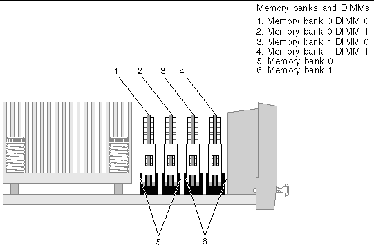
TABLE 1 presents an example of how the Sun SNMP agent models the Netra 440 server component hierarchy. Because this component hierarchy may vary depending on your server and the SNMP agent software version, query the SNMP agent to identify your server's hierarchy. To locate these server components, see the figures in Component and Indicator Identification.
|
FIGURE 4 - item 2 |
||||||
|
FIGURE 4 - item 2 |
||||||
|
FIGURE 4 - item 2 FIGURE 5 - item 5 |
||||||
|
FIGURE 4 - item 2 FIGURE 5 - item 1 |
||||||
|
FIGURE 4 - item 2 FIGURE 5 - item 6 |
||||||
|
FIGURE 4 - item 2 |
||||||
|
FIGURE 4 - item 3 |
||||||
|
FIGURE 4 - item 3 |
||||||
|
FIGURE 4 - item 3 FIGURE 5 - item 5 |
||||||
|
FIGURE 4 - item 3 FIGURE 5 - item 1 |
||||||
|
FIGURE 4 - item 3 FIGURE 5 - item 2 |
||||||
|
FIGURE 4 - item 3 FIGURE 5 - item 6 |
||||||
|
FIGURE 4 - item 3 FIGURE 5 - item 3 |
||||||
|
FIGURE 4 - item 3 FIGURE 5 - item 4 |
||||||
|
FIGURE 4 - item 3 |
||||||
|
FIGURE 4 - item 4 |
||||||
|
FIGURE 4 - item 4 |
||||||
|
FIGURE 4 - item 4 FIGURE 5 - item 5 |
||||||
|
FIGURE 4 - item 4 FIGURE 5 - item 1 |
||||||
|
FIGURE 4 - item 4 FIGURE 5 - item 2 |
||||||
|
FIGURE 4 - item 4 FIGURE 5 - item 6 |
||||||
|
FIGURE 4 - item 4 FIGURE 5 - item 3 |
||||||
|
FIGURE 4 - item 4 FIGURE 5 - item 4 |
||||||
|
FIGURE 4 - item 4 |
||||||
|
FIGURE 4 - item 5 |
||||||
|
FIGURE 4 - item 5 |
||||||
|
FIGURE 4 - item 5 FIGURE 5 - item 5 |
||||||
|
FIGURE 4 - item 5 FIGURE 5 - item 1 |
||||||
|
FIGURE 4 - item 5 FIGURE 5 - item 2 |
||||||
|
FIGURE 4 - item 5 FIGURE 5 - item 6 |
||||||
|
FIGURE 4 - item 5 FIGURE 5 - item 3 |
||||||
|
FIGURE 4 - item 5 FIGURE 5 - item 4 |
||||||
|
FIGURE 4 - item 5 |
||||||
|
FIGURE 3 - item 11 |
||||||
|
PCI Slot 1 (33Mhz 5V) (2nd from left - viewed from front)[1] |
FIGURE 3 - item 10 |
|||||
|
PCI Slot 2 (33/66Mhz 3.3V) (3rd from left - viewed from front)* |
FIGURE 3 - item 9 |
|||||
|
PCI Slot 3 (33Mhz 5V) (3rd from right - viewed from front)* |
FIGURE 3 - item 8 |
|||||
|
PCI Slot 4 (33/66Mhz 3.3V) (2nd from right - viewed from front)* |
FIGURE 3 - item 7 |
|||||
|
FIGURE 3 - item 6 |
||||||
|
FIGURE 4 - item 6 |
||||||
|
FIGURE 1 - item 3 |
||||||
|
FIGURE 1 - item 1 |
||||||
|
FIGURE 1 - item 2 |
||||||
|
FIGURE 3 - item 24 |
||||||
|
FIGURE 3 - item 17 |
||||||
|
FIGURE 3 - item 25 |
||||||
|
FIGURE 3 - item 22 |
||||||
|
FIGURE 3 - item 22 |
||||||
|
FIGURE 3 - item 21 |
||||||
|
FIGURE 3 - item 21 |
||||||
|
FIGURE 3 - item 4 |
||||||
|
FIGURE 3 - item 5 |
||||||
|
FIGURE 2 - item 2 |
||||||
|
FIGURE 2 - item 2 |
||||||
|
FIGURE 2 - item 6 |
||||||
|
FIGURE 2 - item 5 |
||||||
|
FIGURE 2 - item 14 |
||||||
|
FIGURE 2 - item 14 |
||||||
|
FIGURE 2 - item 9 |
||||||
|
FIGURE 2 - item 8 |
||||||
|
FIGURE 2 - item 16 |
||||||
|
FIGURE 2 - item 16 |
||||||
|
FIGURE 2 - item 12 |
||||||
|
FIGURE 2 - item 11 |
||||||
|
FIGURE 4 - item 1 |
||||||
|
FIGURE 4 - item 1 |
||||||
|
FIGURE 1 - item 5 |
||||||
|
FIGURE 3 - item 3 |
||||||
|
FIGURE 3 - item 1 |
||||||
|
FIGURE 3 - item 2 |
||||||
|
FIGURE 1 - item 8 |
||||||
|
FIGURE 1 - item 9 |
||||||
|
FIGURE 1 - item 10 |
||||||
|
FIGURE 1 - item 11 |
||||||
|
FIGURE 2 - item 1 |
||||||
|
FIGURE 2 - item 4 |
||||||
|
HDD0 Service Required Indicator[2] |
||||||
|
FIGURE 2 - item 1 |
||||||
|
FIGURE 2 - item 3 |
||||||
|
FIGURE 2 - item 7 |
||||||
|
HDD1 Service Required Indicator| |
||||||
|
FIGURE 2 - item 3 |
||||||
|
FIGURE 2 - item 15 |
||||||
|
FIGURE 2 - item 10 |
||||||
|
HDD2 Service Required Indicator| |
||||||
|
FIGURE 2 - item 15 |
||||||
|
FIGURE 2 - item 17 |
||||||
|
FIGURE 2 - item 13 |
||||||
|
HDD3 Service Required Indicator| |
||||||
|
FIGURE 2 - item 17 |
||||||
|
FIGURE 3 - item 15 |
||||||
|
FIGURE 3 - item 15 |
||||||
|
FIGURE 3 - item 15 and item 14 |
||||||
|
FIGURE 3 - item 15 and item 12 |
||||||
|
FIGURE 3 - item 15 and item 13 |
||||||
|
FIGURE 3 - item 16 |
||||||
|
FIGURE 3 - item 16 |
||||||
|
FIGURE 3 - item 16 and item 14 |
||||||
|
FIGURE 3 - item 16 and item 12 |
||||||
|
FIGURE 3 - item 16 and item 13 |
||||||
|
FIGURE 3 - item 20 |
||||||
|
FIGURE 3 - item 20 |
||||||
|
FIGURE 3 - item 20 and item 14 |
||||||
|
FIGURE 3 - item 20 and item 12 |
||||||
|
FIGURE 3 - item 20 and item 13 |
||||||
|
FIGURE 3 - item 23 |
||||||
|
FIGURE 3 - item 23 |
||||||
|
FIGURE 3 - item 23 and item 14 |
||||||
|
FIGURE 3 - item 23 and item 12 |
||||||
|
FIGURE 3 - item 23 and item 13 |
||||||
|
FIGURE 1 - item 4 |
||||||
|
FIGURE 1 - item 4 |
||||||
|
FIGURE 1 - item 6 |
||||||
|
FIGURE 1 - item 6 |
||||||
|
FIGURE 1 - item 7 |
||||||
|
FIGURE 1 - item 7 |
||||||
|
FIGURE 3 - item 19 |
||||||
|
FIGURE 3 - item 18 |
||||||
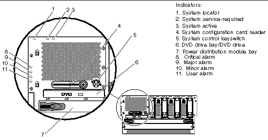
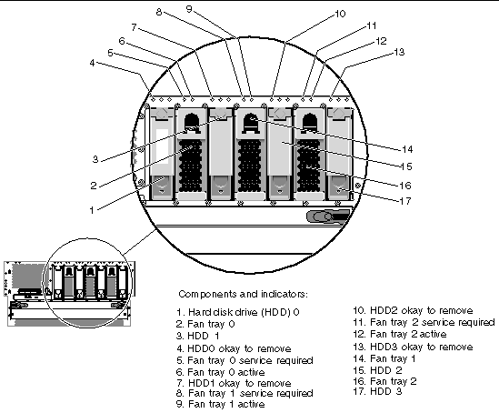
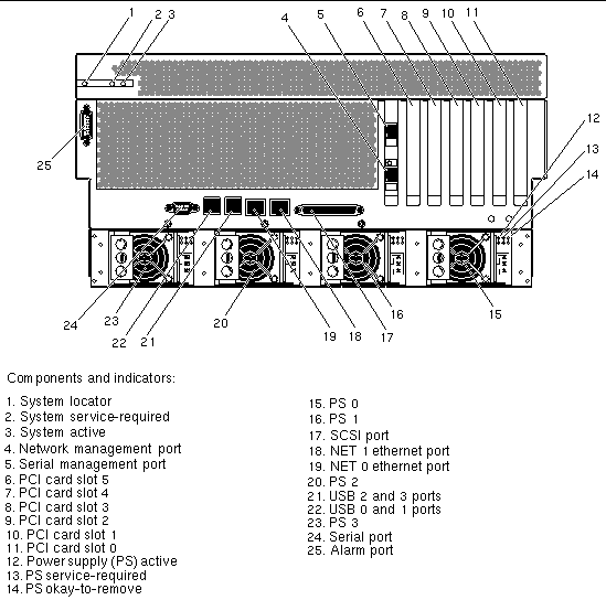
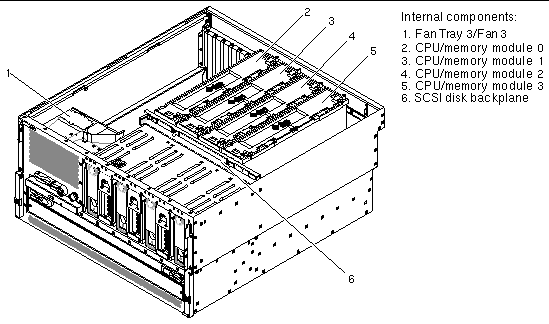
The following figures show the location of the Netra 440 server components. TABLE 1 lists of how the agent models these components in an SNMP hierarchy.
The Netra 440 server fans in the fan trays are identified in the ENTITY-MIB::entPhysicalTable by the entPhysicalDescr of Fan number, where number is a number in the range from 0 to 3. The fans are represented in the following tables that extend the entPhysicalTable:
The fans in fan trays 0-2 contain a tachometer used to indicate the current speed of the fan expressed in revolutions per minute (RPM). The tachometers are identified by their entPhysicalDescr of Fan number Tachometer, where number is a number in the range from 0 to 2 corresponding to the fan tray being monitored. The fan tachometers are represented in the following tables that extend the entPhysicalTable:
If the speed of a fan falls below the threshold indicated by its tachometer's sunPlatNumericSensorLowerThresholdNonCritical value, the fan is considered to have failed and the following will occur:
If the fan recovers from the failure, the following changes will occur:
|
sunPlatEquipmentOperationalState.fan instance[3] |
|
|
entPhysicalDescr.fan instance[4] |
|
|
entPhysicalName of the fan tachometer: Tachometer threshold crossed |
|
|
sunPlatEquipmentAlarmStatus.fan instance[5] |
|
|
entPhysicalDescr.LED instance[6] |
|
|
sunPlatAlarmState.LED instance* |
|
You can detect fan status using the following mechanisms:
The power supplies are identified in the ENTITY-MIB::entPhysicalTable by the entPhysicalDescr of Power Supply number where number is 0, 1 2 or 3. The power supplies are represented in the SUN-PLATFORM-MIB::sunPlatEquipmentTable.
Each power supply contains the following sensors:
These sensors are represented in the following tables:
If any of the power supply sensors detect a fault the following changes will occur:
Recovery from the power supply fault will result in the following changes:
|
entPhysicalDescr.ps sensor instance[7] |
|
|
sunPlatEquipmentOperationalState.ps instance[8] |
|
|
entPhysicalDescr.ps instance[9] |
|
|
entPhysicalDescr.ps instance[10] |
|
|
sunPlatAlarmState.LED instance[11] |
|
You can use the following mechanisms to detect power supply status:
The Netra 440 server has four dry contact alarm relays and four corresponding LED indicators. The alarm relays are identified in the ENTITY-MIB::entPhysicalTable by the following entPhysicalDescr values:
The alarm LED indicators are identified in the ENTITY-MIB::entPhysicalTable by the following entPhysicalDescr values:
The alarm relays and the alarm LED indicators are represented in the
SUN-PLATFORM-MIB::sunPlatAlarmTable which extends the
ENTITY-MIB::entPhysicalTable.
The alarm relay state cannot be changed using SNMP set commands. However, the alarm relay state can be changed using the Sun Advanced Lights Out Manager (ALOM) setalarm command. For more information about ALOM commands, refer to the Sun Advanced Lights Out Manager Software User's Guide for the Netra 440 Server (817-5481-xx).
The alarm relay states can also be changed using the alarm relay output application programming interface (API). For information about this API, refer to the Netra 440 Server System Administration Guide (817-3884-xx).
If one of the alarm relays changes its state, the sunPlatAlarmState values associated with the relay and its corresponding indicator change state, and sunPlatAttributeChangeInteger traps will be generated in the format shown in TABLE 11.
|
entPhysicalDescr.instance[12] |
|
Copyright © 2004, Sun Microsystems, Inc. All rights reserved.