| C H A P T E R 4 |
|
Maintaining the Workstation |
This chapter provides instructions describing how to add, replace and configure the components in the workstation after it has been set up. The following sections are included in this chapter:
Before removing the system's left-side access panel, read the following sections. These sections contain important ESD precautions, along with preinstallation and postinstallation instructions.
Electrostatic discharge (ESD) can damage your processor, disk drives, expansion boards, and other components. Always observe the following precautions before you install a system component:
1. Do not remove a component from its protective packaging until you are ready to install it.
2. Wear a wrist strap and attach it to the system chassis ground, or any metal part of the system, before handling components.
3. Disconnect the AC power cord from the system before removing or replacing any of the system components.
Always perform the following steps before you install any component:
1. Turn off the system and all of the peripherals connected to it.
2. Unplug the AC power cable from the system.
Standby power is applied to the motherboard whenever an AC power cord is connected.
3. Follow the ESD precautions described above when handling a system component.
See the following section for specific installation instructions.

|
Caution - Failure to properly turn off the system before you start installing components may cause serious damage. |
Perform the following steps after installing a workstation component:
1. Ensure that all of the components are installed as described in the step-by-step instructions.
2. Reinstall any PCI cards or peripherals that you had previously removed.
3. Reinstall the system's left-side panel and front bezel.
4. Connect all external cables to the system.

|
Caution - If the left-side panel and hard disk drives are removed, do not operate the workstation for more than ten minutes. Improper cooling airflow might damage the system's components. |

|
Caution - Before you proceed, turn off your system and all of the peripherals connected to it. Refer to Section 4.2.2, Preinstallation Instructions. |
|
Note - The illustrations used in this section show a single-processor (1P) system chassis. |
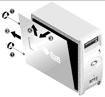
The left-side access panel must be removed to gain access to the system's internal components. See FIGURE 4-1 when performing this procedure.
1. Turn off the system and all of the peripherals connected to it.
2. Loosen the two captive thumbscrews located on the edge of the left-side panel closest to the rear panel (1).
3. Slide the panel towards the rear of the workstation (2). Tilt the top edge of the panel out (3) and then up (4) to remove it from the chassis.
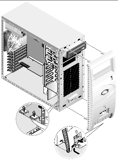
See FIGURE 4-2 when performing this procedure.
1. Remove the left-side access panel.
2. Press the plastic retention clips, on the bottom of the bezel, upward to release them from the tabs on the inside of the front chassis.
3. Tilt the bottom edge of the bezel away to disengage it from the chassis.
4. Pull the bezel away from the chassis.
See FIGURE 4-3 to locate components before performing the remove and replace procedures.
The following system components may be installed or replaced by the customer.
|
Note - The motherboard should be replaced only by trained field service technicians. |
|
Note - The replacement hard disk drive must be configured the same as the drive being replaced. |
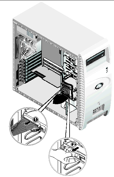
This procedure describes how to remove a hard disk drive. See FIGURE 4-4 when performing this procedure.
To remove the hard disk drive:
1. Turn off the system and all of the peripherals connected to it, then unplug the AC power cord from the system.
2. Remove the left-side access panel.
3. Disconnect the power and data cables from the drive (1).
4. Grasp the hard-disk-drive carrier handle at its center (2), then gently withdraw the drive from the cage.
5. If you are replacing the hard drive, unfasten the four screws securing the hard disk drive to the carrier and remove the drive.
Installation is the reverse of this procedure.
To install a second hard disk drive when one hard disk drive is already installed:
1. Turn off the system and all of the peripherals connected to it, then unplug the AC power cord from the system.
2. Remove the left-side access panel.
3. Remove the empty drive carrier from the drive cage, if necessary.
4. Insert the hard disk drive into the drive carrier, and fasten the four screws to secure the hard disk drive to the carrier.
5. Gently push the hard disk drive carrier into the drive cage.
6. Follow the instructions for the type of hard disk drive that you are installing:
a. Change the target ID to 1 on the newly installed SCSI drive and leave the target ID set at 0 on the previously installed drive.
Refer to the manufacturer's documentation that comes with the hard disk drive to determine the exact jumper settings.
b. Disconnect the SCSI data cable from the drive that was previously installed in the workstation and connect it to the newly installed drive.
c. Connect the remaining SCSI cable to the previously installed drive.
a. Change the jumper settings so that the drive that was installed first is the master and the newly installed drive is the slave.
Refer to the manufacturer's documentation that comes with the hard disk drive to determine the exact jumper settings.
b. Connect the IDE data cable to the newly installed drive.
7. Connect the power cable to the newly installed hard disk drive power connector.
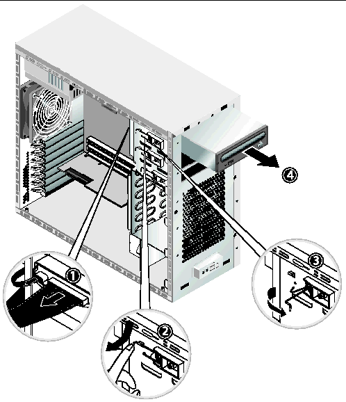
This procedure describes how to remove the CD/DVD drive. See FIGURE 4-5 when performing this procedure.
|
Note - The replacement CD/DVD drive must be configured the same as the drive being replaced. |
1. Turn off the system and all of the peripherals connected to it, then unplug the AC power cord from the system.
2. Remove the left-side access panel.
4. Disconnect the power and IDE data cables from the CD/DVD drive (1).
5. Simultaneously push the drive retaining lever inward and down to release the lever from its retaining hook (2).
6. Rotate the lever towards the front of the chassis until the pin, at the other end of the lever, is freed from its hole near the retaining hook (3).
7. Gently pull out the CD/DVD drive from the chassis (4).
8. Place the CD/DVD drive on a static-dissipating work surface or inside an anti-static bag.
Installation is the reverse of this procedure.
|
Note - When reinstalling the CD/DVD drive into the drive bay, ensure that the hole in the drive's case is aligned with the hole in the chassis, from which the drive retaining lever pin was withdrawn (refer to FIGURE 4-5). |
|
Note - Ensure that the IDE jumper, on the rear of the CD/DVD drive, is set to CS (Cable Select). |
Your system comes preinstalled with a CD-RW/DVD-ROM drive. Below the CD-RW/DVD-ROM drive is an empty 5.25-inch half-height bay, enabling you to install an additional storage device. Refer to FIGURE 4-5 when performing this procedure.
To remove an optional storage device:
1. Turn off the system and all of the peripherals connected to it, then unplug the AC power cord from the system.
2. Remove the left-side access panel.
5. Simultaneously push the drive retaining lever inward and down to release the lever from its retaining hook (2).
6. Rotate the lever towards the front of the chassis until the pin, at the other end of the lever, is freed from its hole near the retaining hook (3).
7. Slide the 5.25-inch drive with preinstalled carrier into the drive bay.
8. Lock the drive in the bay by rotating the drive retaining lever towards the rear of the chassis.
|
Note - When reinstalling the CD/DVD drive into the drive bay, ensure that the hole in the drive's case is aligned with the hole in the chassis, from which the drive retaining lever pin was withdrawn (refer to FIGURE 4-5). |
9. Press the end of the lever down and inward, until it is captured by the retaining hook.
10. Connect the power and IDE data cables to the rear of the new drive.
This section describes how to remove or replace a CPU and heatsink. The remove and replace procedures are identical for both CPU 0 (on the motherboard) and CPU 1 (on the optional mezzanine card).
|
Note - Before removing a CPU from the motherboard, create a backup file to preserve all important data. |
1. Turn off the system and all of the peripherals connected to it, then unplug the AC power cord from the system.
2. Remove the left-side access panel.
3. Gently lay the system on its right side on a stable, non-slip surface.

|
Caution - The heatsink can become extremely hot. Allow a few minutes for the heatsink to cool before attempting this procedure. |
4. Disconnect the CPU fan cable from its connector.
If you are removing CPU 0, on the motherboard, see FIGURE 4-6.
If you are removing CPU 1, on the mezzanine card, see FIGURE 4-7.
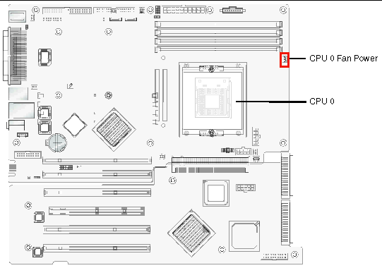
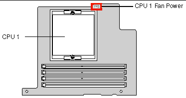
5. Loosen the two screws that hold the heatsink/fan assembly to the motherboard (see (1) on FIGURE 4-8), then pivot the retaining clips outward (2).
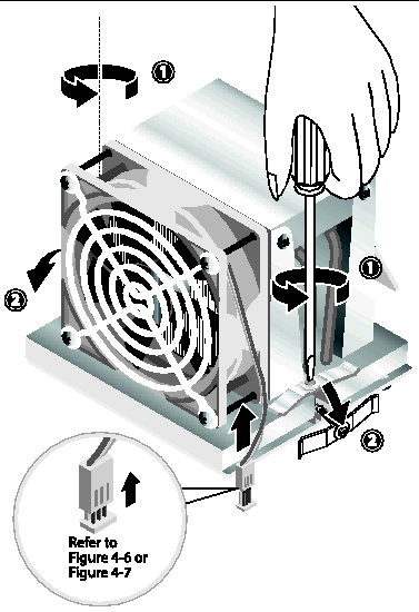
6. Twist the heatsink/fan assembly to the right or the left, in order to break the seal with the thermal grease.
7. Lift the heatsink/fan assembly straight up and withdraw it from the board (see FIGURE 4-9).
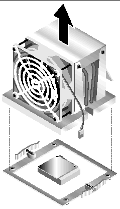
8. Place the heatsink upside down on a flat surface to prevent the thermal grease from contaminating other components.
9. Use an alcohol pad to clean the thermal grease from both the bottom of the heatsink, and the top of the CPU.
|
Note - Failure to clean the CPU before removing it could result in the accidental contamination of the CPU or other components. |
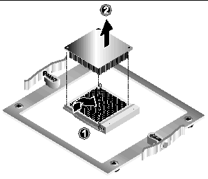
10. First depress, then pull the CPU socket retainer lever up to the fully open, perpendicular position (see (1) on FIGURE 4-10).
11. Lift the CPU out of the socket, leaving the retainer lever in the open position (2).
To install a heatsink and CPU:
1. Observe the ESD precautions and preinstallation procedures described in Section 4.2.1, ESD Precautions.
2. Ensure that the CPU socket retainer lever is in the fully open, upright position.
3. Align the CPU to its socket so that pin 1 of the CPU (indicated by the notched corner) is aligned with hole 1 of the socket, (indicated by the arrow in the corner of the socket). See FIGURE 4-11.
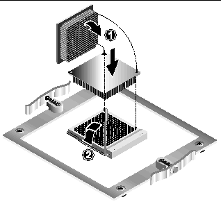
4. Insert the CPU into the socket.
|
Note - When correctly aligned, the CPU should drop effortlessly into the socket. Do not attempt to force the CPU into the socket in order to seat it. |
5. When the CPU is positioned in the socket, press down on the socket retainer lever to lock the CPU in place (see (2) on FIGURE 4-11).
6. Use the syringe that is supplied with the new or replacement CPU to apply approximately 0.1 ml of thermal grease to the center of the top of the CPU.
7. Inspect the heatsink/fan assembly for dust and lint. Clean if necessary.
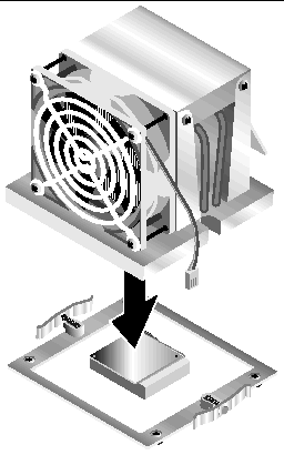
8. Carefully position the heatsink/fan assembly on the CPU, aligning it with the mounting posts to reduce movement after it makes initial contact with the layer of thermal grease (see FIGURE 4-12).

|
Caution - If the heatsink assembly is moved too much during its installation, the layer of thermal grease might not be distributed evenly, leading to component damage. |
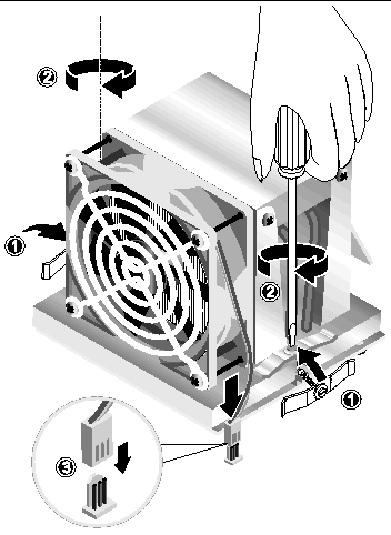
9. Position the retaining clips over the heatsink/fan assembly (see (1) on FIGURE 4-13).
10. Tighten the securing screws, alternating from side to side, until the screws are completely tightened (2).
11. Connect the CPU fan cable to the connector on the motherboard (3).
This section contains instructions for removing and installing a dual in-line memory module (DIMM). See FIGURE 4-14 when performing this procedure.
|
Note - Before removing any DIMMs from the motherboard, create a backup file to preserve any important data. |
1. Turn off the system and all of the peripherals connected to it, then unplug the AC power cord from the system.
2. Remove the left-side access panel.
3. Gently lay the system on its right side on a stable, non-slip surface.
4. Identify the location from which you will remove a DIMM.
5. Remove the DIMM by pressing down on the ejector bars at both ends of the DIMM socket.
|
Note - Place your forefingers on the top of the DIMM before pressing down on the ejector bars, to gently disengage the DIMM from the socket. |
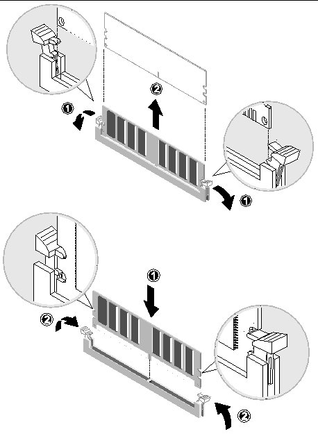
Installation is the reverse of this procedure.
|
Note - The DIMM socket is slotted to ensure proper installation. |
If you are installing a 2 GB DIMM into a workstation in which a 2 GB DIMM has not previously been installed, you need to make sure that the workstation is running BIOS version R1B0S4 or later before installing the DIMM.
1. Determine your BIOS version.
Press the F2 key while the workstation is booting up to enter the BIOS setup screen
b. Select the product information option.
a. Download the ISO of the Supplemental CD V1.1 from the following web site:
http://www.sun.com/desktop/workstation/w1100z/downloads.html
c. Insert the CD into the Sun Java Workstation W1100z or W2100z.
4. When the Supplemental CD main menu is displayed, select option 2 to update the BIOS.
5. Follow directions on the screen.
6. Install the DIMMs as instructed in Section 4.5.5.1, Replacing DIMMs.
The system automatically detects the amount of memory installed. Run the BIOS setup to view the new value for total system memory and make a note of it.
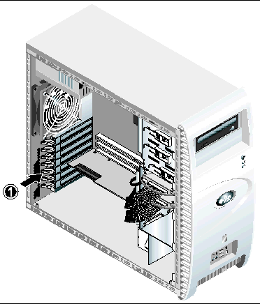
This procedure describes how to install a typical PCI card (including the host bus adapter) or AGP card. PCI and AGP cards may vary in the way in which they are installed in the system. For example: PCI cards may be either full-length cards or half-length cards; AGP cards are secured in the AGP card slot with a latch. Visually inspect each card to determine its mounting requirements before beginning this procedure.
1. Turn off the system and all of the peripherals connected to it, then unplug the AC power cord from the system.
2. Remove the left-side access panel.
3. Gently lay the system on its right side on a stable, non-slip surface.
4. Refer to the Service Label, attached to the inside of the access panel, to choose an empty card slot that is compatible with the card that you are installing.
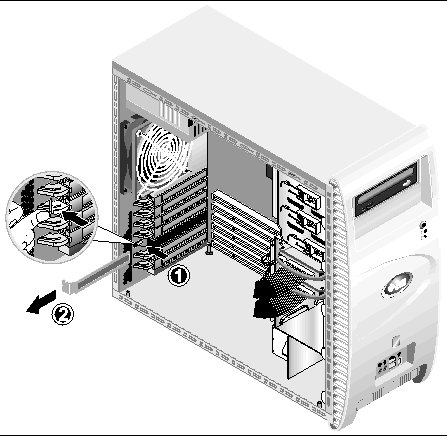
5. Working from inside the chassis, compress the blue retention clip (securing the selected slot cover) until it passes through the cutout in the rear panel (see (1) on FIGURE 4-15). Then pivot the clip outwards.
6. Pull out the slot cover (see (2) on FIGURE 4-15).
7. Remove the PCI or AGP card from its protective packaging. If necessary, lay the card on an anti-static surface until you are ready to install it.
8. Refer to the bullet below that corresponds to the card you are installing:
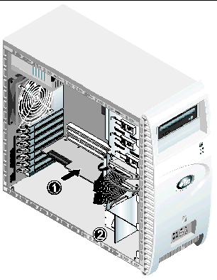
a. Position the card over the selected slot (see (1) on FIGURE 4-16). If you are installing a full-length card, slide the forward edge of the card into one of the indentations in the card guide, located immediately below the drive cage (see (2) on FIGURE 4-16).
b. Press down on the card until it is completely seated in the slot.
a. Make sure that the card latch, at the forward end of the AGP slot, is completely opened (see (1) on FIGURE 4-18).
b. Position the card in the selected slot (see (2) on FIGURE 4-17). Ensure that the notch, on the bottom right corner of the card, engages the latch.
c. Press down on the card until it is completely seated in the slot.
d. Pivot the latch up and towards the rear of the chassis to secure the card in place.
|
Note - If the latch cannot be engaged with a minimum of force, the card is not correctly seated. Remove the card, reinsert it, and attempt to engage the latch again. |
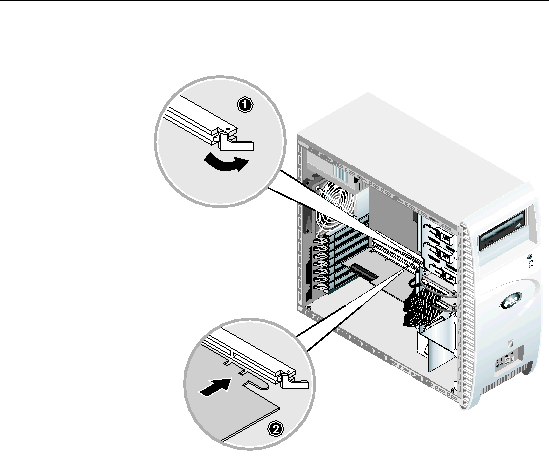
9. Rotate the retention clip back into the chassis until the clip snaps into place (refer to (1) on FIGURE 4-18).
10. Connect any necessary adapters or cables to the card.
Removal is the reverse of this procedure.
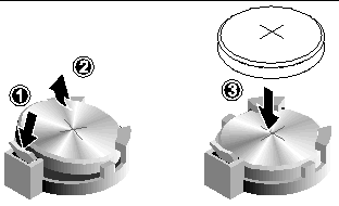
To remove and install the battery (see FIGURE 4-19):
1. Turn off the system and all of the peripherals connected to it, then unplug the AC power cord from the system.
2. Remove the left-side access panel.
3. Gently lay the system on its right side on a stable, non-slip surface.
4. If a mezzanine card is present, remove it and/or the PCI card in Slot 1 to gain access to the battery socket.
5. Insert a small flathead screwdriver between the battery and spring latch to dislodge the battery from its socket (1).
6. Lift up the battery to remove it (2).
7. Insert a new battery with the positive sign (+) facing up, and ensure that it is seated completely (3).
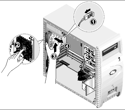
To remove the system fan (see FIGURE 4-20):
1. Turn off the system and all of the peripherals connected to it, then unplug the AC power cord from the system.
2. Remove the left-side access panel.
3. Gently lay the system on its right side on a stable, non-slip surface.
4. Disconnect the system fan's power connector from the motherboard (1).
5. Working from outside the rear of the chassis, press the spring-loaded button, at the center of the system fan (2).
6. While holding the button in, slide the fan up (3) and withdraw it from the mounting slots (4).
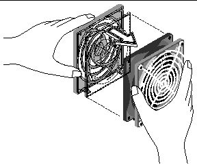
7. Detach the fan from its frame by unclasping the four tabs on the frame before pulling the fan away.
Installation is the reverse of this procedure.
To remove the power supply (see FIGURE 4-22):
1. Turn off the system and all of the peripherals connected to it, then unplug the AC power cord from the system.
2. Remove the left-side access panel.
3. Gently lay the system on its right side on a stable, non-slip surface.
4. Unfasten the connectors from the motherboard and release the cable management straps (1).
5. Unfasten the 4-pin power connectors attached to the DVD drive and any other I/O devices present.
6. Unfasten the two screws that attach the rear of the power supply to the right side of the chassis (2).
7. Working from outside the rear of the chassis, unfasten the four mounting screws (3) and withdraw the power supply through the interior of the system chassis (4).
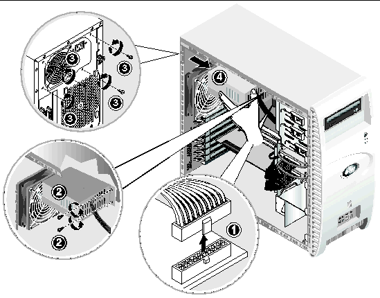
Installation is the reverse of this procedure.
To remove the USB audio card assembly (see FIGURE 4-23):
1. Turn off the system and all of the peripherals connected to it.
2. Remove the left-side access panel and the front bezel.
3. Place the system unit on a flat, stable surface.
4. Disconnect the audio, USB, and IEEE 1394 cables from the audio board (1).
5. Working from the front of the chassis, unfasten the single screw securing the USB audio card assembly to the system's front panel (2).
6. Gently lift the audio assembly up and slightly away from the front panel.
7. Remove the two screws that hold the audio board to the metal frame (3).
8. Withdraw the audio card from the metal frame (4).
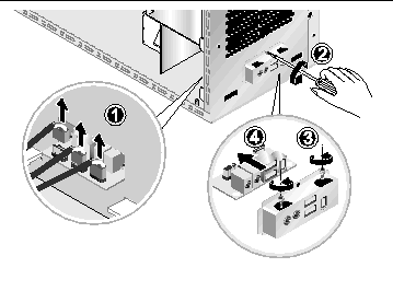
Installation is the reverse of this procedure.
To remove the operator's panel:
1. Turn off the system and all of the peripherals connected to it, then unplug the AC power cord from the system.
2. Remove the left-side access panel and the front bezel.
3. Gently lay the system on its right side on a stable, non-slip surface.
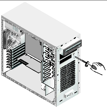
4. Working from the front of the chassis, unfasten the single screw securing the operator's panel to the front of the chassis (see FIGURE 4-24).
5. Working from inside the chassis, grasp the operator panel cables and gently pull the panel into the chassis.
6. Disconnect the two connectors attaching the operator's panel to the motherboard and withdraw the operator's panel from the chassis (see FIGURE 4-25).
Installation is the reverse of this procedure.
The following list of system cables have a connector at each end, and so may be removed or installed by the customer. All other cables are permanently attached to a system component at one end and must be removed or replaced along with the component.
Each cable connector on the motherboard and extender card is labeled to help you identify the cable to which it should be connected.
To remove and install system cables:
1. Turn off the system and all of the peripherals connected to it, then unplug the AC power cord from the system.
2. Remove the left-side access panel.
3. Gently lay the system on its right side on a stable, non-slip surface.
4. Ensure that all cable routing is correct, and that all of the cable connectors are properly seated, before re-installing the left-side access panel.
Use FIGURE 4-26 to identify the cable to be replaced.
1. Turn off the system and all of the peripherals connected to it, then unplug the AC power cord from the system.
2. Remove the left-side access panel.
3. Gently lay the system on its right side on a stable, non-slip surface.
4. Remove the heatsink/fan assembly (refer to Section 4.5.4, Replacing a CPU) in order to expose four of the mezzanine card's mounting screws.
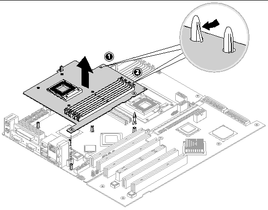
5. Unfasten the six screws securing the mezzanine card to the motherboard (FIGURE 4-27).
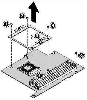
6. Use a pair of needle-nose pliers to push in the latch on each of the two white standoffs holding the card to the motherboard (see FIGURE 4-28).

|
Caution - When you push in the mezzanine card standoffs, make sure that you do not damage the capacitors that are located near the standoffs. |
7. Lift the mezzanine card straight up to release it from the two connectors on the motherboard.
8. Remove the CPU (refer to Section 4.5.4, Replacing a CPU).
9. Remove the DIMMs (refer to Section FIGURE 4-14, Removing and Installing a DIMM).
Installation is the reverse of this procedure
This procedure describes how to remove the Extender card.
1. Turn off the system and all of the peripherals connected to it, then unplug the AC power cord from the system.
2. Remove the left-side access panel.
3. Gently lay the system on its right side on a stable, nonslip surface.
4. Remove any PCI Cards installed on the extender card (refer to Section 4.5.6, Installing a PCI or AGP Card).
5. Pivot the front card guide (located below the drive cage) up and towards the front of the chassis.
6. Disconnect the SCSI data cable and the power connector from the extender card (see FIGURE 4-29).
7. Unfasten the audio cable (coming from the USB panel at the front of the chassis) from the FRONT_AUDIO connector on the motherboard.
8. Release the audio cable from the cable clip, located at the bottom left corner of the chassis, and lay the cable over the front of the chassis.
9. Unfasten the 5 screws securing the extender card to the system chassis (see (1) through (5) on FIGURE 4-30).
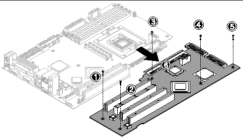
10. Gently lift the side of the extender card, that is next to the bottom of the chassis, approximately 1 inch.
11. Pull the extender card away from the motherboard to disengage the connector (see (6) on FIGURE 4-30). Withdraw the extender card from the system chassis and place the card on a suitable antistatic surface.
Installation is the reverse of this procedure.
|
Note - The motherboard is not a CRU and should be replaced only by trained field service technicians. |
1. Turn off the system and all of the peripherals connected to it, then unplug the AC power cord from the system.
2. Remove the left-side access panel.
3. Gently lay the system on its right side on a stable, non-slip surface.
4. Remove any PCI cards installed on either the extender card or the motherboard (see Section 4.5.6, Installing a PCI or AGP Card).
5. Remove the extender card, as described in Section 4.5.14, Replacing the Extender Card.
6. Remove the mezzanine card (if present) as described in Section 4.5.13, Replacing the Mezzanine Card.
7. Disconnect all cables attached to the motherboard (see FIGURE 4-31).
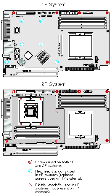
8. Unfasten the motherboard from the chassis.
a. Use a hex-nut driver to remove 6 hex-head standoffs.
b. Remove five Philips head screws.
c. Use needle-nosed pliers to release the two plastic standoffs.
|
Note - Do not remove the four screws that secure the CPU 0 heatsink/fan assembly mounting to the motherboard. |
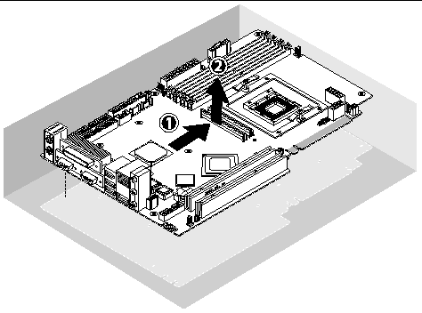
9. Slide the motherboard towards the front of the chassis (see (1) on FIGURE 4-33) and then lift it up to withdraw it (2).
Refer to the following sections to remove and replace the CPU and memory:
Installation is the reverse of this procedure.

|
Caution - Observe proper ESD precautions when handling the new motherboard. |
Copyright © 2004, Sun Microsystems, Inc. All Rights Reserved.