| C H A P T E R 10 |
|
Installing Solaris x86 |
This chapter tells you how to install Solaris x86 onto a Sun Fire B100x or B200x server blade. It contains the following sections:
The B100x and B200x blades use a PXE-based network installation method to receive the Solaris x86 operating system. PXE booting is supported by DHCP services, and this means that there are a number of setup steps you need to perform involving the DHCP server. Also, the Network Install Server and the DHCP server need to be configured for each individual blade, otherwise the network installation will not work. The instructions in this chapter tell you what to do to get to a point where you can inititiate an interactive Solaris installation or a Jumpstart installation on the blade. The chapter refers you to the Solaris 9 Installation Guide for instructions about the interactive part of the Solaris installation.
The tasks that you will perform in this chapter are as follows:
For each blade you are installing, you will also perform the following steps in Section 10.4, Configuring the Install Server and the DHCP Server to Install Solaris x86 Onto Each Blade:
1. Connect a network port on the SSC to a subnet containing both the Network Install Server you intend to use and the DHCP server you intend to use to allocate IP addresses to the B100x or B200x server blade.
If you have a redundant SSC in the blade system chassis, duplicate this connection on the second SSC.
2. Find out the MAC address of the first interface on the blade you intend to install Solaris x86 onto.
a. Log into the active System Controller by following the instructions in Chapter 2 of the Sun Fire B1600 Blade System Chassis Software Setup Guide if you are logging into a brand new chassis in its factory default state.
Otherwise log in using the user name and password assigned to you by your system administrator.
where the : character (in the leftmost column) indicates omitted data. The MAC address listed for each blade is the MAC address of the first interface (by default, bge0).
For an installation that uses the first network interface on the blade, you only need to know the MAC address of the first network interface. Make a note of this MAC address.
If you intend to use the second, third, or fourth interface instead, you need to calculate the MAC address for that interface (see Section 10.12, Installing Solaris x86 Onto a Blade by Using the Second, Third, or Fourth Network Interface).
3. Set up a Network Install Server for Solaris x86 by following the instructions in the Solaris 9 Installation Guide.
Make a note of the IP address of the Network Install Server that your blades will install their x86 operating system from.
4. Make sure the DHCP server you intend to use is properly set up and functioning.
For information about setting up a Solaris DHCP server, refer to the Solaris DHCP Administration Guide.
|
Note - Make sure you have updated your DHCP server with the latest DHCP patches available at: http://sunsolve.sun.com. |
5. If you want the DHCP server to allocate IP addresses dynamically to the server blade, then reserve a block of addresses on the DHCP server for this purpose.
For information about how to do this, refer to the Solaris DHCP Administration Guide.
6. Read the latest Product Notes for the chassis and blades to find out whether you need to download any patches for the version of Solaris x86 that you intend to install onto the blade.
Check the following location on the web:
http://www.sun.com/servers/entry/b100x/
The information you require is in the section of the Product Notes entitled "Installing the Solaris x86 Operating System Onto a Server Blade".
This section tells you how to configure the option strings that are required on the DHCP server to support booting of the B100x and B200x blades. It also tells you how to configure the global PXE boot client. If the required options strings are already defined on the DHCP server and the PXE boot client is already correctly specified, proceed to Section 10.4, Configuring the Install Server and the DHCP Server to Install Solaris x86 Onto Each Blade.
1. Log into the Network Install Server as root, and start the DHCP Manager GUI by typing:
where mydisplay is the name of the system (for example, a desktop workstation) that you are using to display the DHCP Manager's GUI (Graphical User Interface).
2. If the following option names are not already defined in the DHCP server, add them:
SinstNM, SinstIP4, SinstPTH, SrootNM, SrootIP4, SrootPTH, BootFile, SbootURI, BootSrvA
|
Note - If you intend to perform a Jumpstart installation of Solarix x86, you also need to add definitions for SsysidCF and SjumpsCF. |
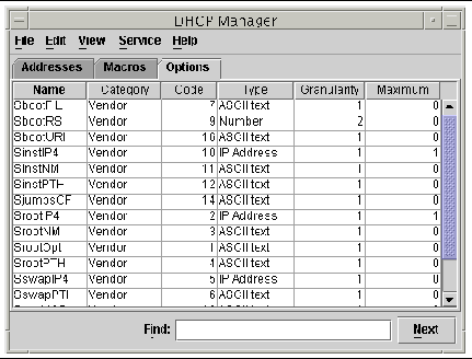
a. Find out which option names are already defined in the DHCP server by clicking the Options tab in the DHCP Manager's main window (see FIGURE 10-1).
b. Use the command line to add (using -A, as shown below) or modify (using -M instead of -A) the required option strings.
To do this, continue as root on the Network Install Server, and in a terminal window type the command for each option you require. The full list of required options is shown in FIGURE 10-2.
|
Note - that, although some of the required DHCP options strings might already have been defined on your DHCP server, SbootURI is a new option string that has not been used before on Sun platforms. |

|
Caution - When you are configuring the DHCP option strings, make sure you allocate the option string code correctly for each option. These values are used by the network bootstrap process and the process will fail if the values are not specified correctly. The option code is the fourth value from the right on the command line. For example, the code for SbootURI is 16 (see FIGURE 10-2). If you specify values that are different from the values in FIGURE 10-2, the blades will not be bootable from the network. |
3. Verify that you have specified the DHCP option strings correctly.
The : character beneath the first user prompt in FIGURE 10-3 indicates omitted data.
|
Note - FIGURE 10-3 shows output relating to the DHCP options strings (output relating to the macros has been omitted and the omission is indicated by the : character). Note that different vendor names (for example, SUNW.Ultra-1, SUNW.Ultra-30, SUNW.i86pc) might be associated with each option string in your configuration, but that the user-specified values for the other fields of the command line must be exactly as printed in FIGURE 10-3. For example, the last four values for the SbootURI option need to be 16, ASCII, 1, 0. |
For further information about adding options, see refer to the Solaris DHCP Administration Guide.
4. Proceed to Section 10.3.2, Adding the Global PXE Macro for Solaris x86 to the DHCP Server.
|
Note - The instructions in this section only need to be performed once on the DHCP server. If you already have the PXE macro correctly defined for Solaris x86, you can skip this section and proceed to Section 10.1, Overview of the Solaris x86 Installation Procedures. However, it is critical that the macro is defined correctly, so if you are in any doubt follow the instructions in this section. For equivalent CLI (command-line interface) commands, refer to Section 10.11.3, Using the DHCP Manager's Command-line Interface Instead of the GUI. |
To define the global PXE macro:
1. In the main window of DHCP Manager's GUI, click the Macros tab, and select Create from the Edit menu.
2. In the Name field of the Create Macro window, type the name of the PXE macro: PXEClient:Arch:00000:UNDI:002001
3. Complete the other fields in the Create Macro window
a. In the Option Name field, type BootSrvA.
b. In the Option Value field, type the IP address of your Network Install Server.
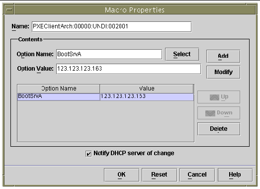
To view the properties of the macro you have created, select it from the list of macros displayed on the left of the Macros tab, then select Properties from the Edit menu (see FIGURE 10-4).
|
Note - The global PXE macro has only a single property defined: BootSrvA. |
4. Proceed to Section 10.4, Configuring the Install Server and the DHCP Server to Install Solaris x86 Onto Each Blade.
Before following the instructions in this section, make sure you have completed all the steps in the previous sections of this chapter, and that you have performed any steps relating to the Solaris x86 installation in the latest Product Notes.
The tasks in this section need to be performed for every blade that you intend to install Solaris x86 onto. They are as follows:
After performing Step 7, you will need to perform the following tasks:
1. Make a note of the MAC address of the blade you are intending to install Solaris x86 onto (see Section 10.1, Overview of the Solaris x86 Installation Procedures).
If you are intending to use an interface other than the first network interface on the blade, see Section 10.12, Installing Solaris x86 Onto a Blade by Using the Second, Third, or Fourth Network Interface.
2. Log in as root to the system you are using as the Network Install Server, and run the add_install_client script.
When you run this script make sure that you use the correct bootpath parameters for the server blade.
The correct bootpath parameter for a B100x blade is shown in FIGURE 10-5.
The correct bootpath parameter for a B200x blade is shown in FIGURE 10-6.
|
Note - The -b option for the add_install_client command is new. For information about this option, see Section 10.13, The New add_install_client -b Option. |
If you are intending to perform a Jumpstart installation, you need to use additional parameters on the command line when you run the add_install_client script.
For information about the parameters to use for Jumpstart, refer to Section 10.9, Preparatory Steps for Setting up a Jumpstart Installation for a Blade, and to Section 10.10, Configuring a Jumpstart Installation.
 For a B100x blade with the MAC address 00:03:ba:29:f0:de, see the sample command in FIGURE 10-5.
# cd install-dir-path/Solaris_9/Tools # ./add_install_client -d -e "00:03:ba:29:f0:de" \ > -b "input-device=ttya" -b "output-device=ttya" \ > -b "bootpath=/pci@0,0/pci108e,16a8@8" \ > i86pc |
where install-dir-path is the location of your install image.
|
Note - In the sample commands in this step, the `\' character tells the operating system that the command is being continued on the next line. |
|
Note - If you are configuring multiple blades, you might want to create a wrapper script to run the add_install_client command for each blade (see Section 10.11.1, Calling the add_install_client Utility From a Wrapper Shell Script). |
 For a B200x blade with the MAC address 00:03:ba:2d:d4:a0, see the sample command in FIGURE 10-6.
FIGURE 10-7 shows sample output from the add_install_client script executed with a bootpath for the B100x blade.
The sample command illustrated in FIGURE 10-7 uses the new (-b) boot option. For information about the arguments taken by this option, and required for the PXE boot process to work on a blade, see Section 10.13, The New add_install_client -b Option at the end of this chapter.
3. Make a note of the options listed in the output from the add_install_client script (see FIGURE 10-7).
You need to note the option names and their values.
The output from the add_install_client script is displayed in three sections. The first contains text explaining that the previous install configurations associated with the specified client are being cleaned up in preparation for the new install configuration. The second contains a list of options that are specific to the client. These are the options that you need to write down; you will need to add them as properties (in later steps) to the client-specific DHCP macro. Finally, the third contains information concerning the global PXE boot macro (including the name of the global macro).
4. Make sure the required option names are defined in the DHCP server.
You defined these in Section 10.3.1, Adding the Required Option Strings to the DHCP Server.
5. Make sure the global PXE macro for Solaris x86 has been correctly added to the DHCP server.
You added this in Section 10.3.2, Adding the Global PXE Macro for Solaris x86 to the DHCP Server.
6. Create the client-specific macro for the blade you are intending to install Solaris x86 onto.
To use the command-line interface, see Section 10.11.3, Using the DHCP Manager's Command-line Interface Instead of the GUI.
To use the GUI, do the following:
a. If you are not already running the DHCP Manager GUI, log into the Network Install Server as root, and start the DHCP Manager GUI by typing:
where mydisplay is the name of the system (for example, a desktop workstation) that you are using to display the DHCP Manager's GUI (Graphical User Interface).
b. In the DHCP Manager main window, click the Macros tab, and select Create from the Edit menu.
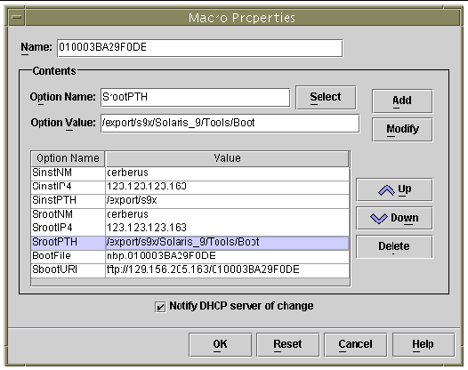
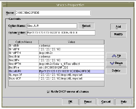
The blades are indentified to the DHCP server by a client identifier (ID) string. This string contains the digits 01 followed by the MAC address of the blade's network interface (however, the string does not include any colons). In the example we have been using this MAC address is 00:03:ba:29:f0:de. The client ID for the blade is therefore 010003BA29F0DE (see FIGURE 10-7).
c. With the Create Macro window open:
i. In the Name field of the Create Macro window, type the client ID for your blade.
In the example we have been using (see FIGURE 10-7), the client ID is 010003BA29F0DE, therefore the name of the macro for this sample client is 010003BA29F0DE.
ii. In the Contents section of the Create Macro window, click the Select button.
iii. From the drop-down Category list, select Vendor.
iv. Select SinstNM and click OK.
v. Delete any existing information in the Option Value field.
vi. Using the data you wrote down in Step 3 (in this section), type the correct Option Value for SinstNM.
viii. Repeat Step iv through Step vii for SinstIP4, SinstPTH, SrootNM, SrootIP4, SrootPTH, and SbootURI.
ix. When you have configured the seven Vendor options for the client, click Select in the Create Macro window and, from the drop-down Category list, select Standard.
x. Select BootFile and click OK.
xi. Delete any existing information in the Option Value field.
xii. Using the data you wrote down in Step 3 (in this section), type the correct Option Value for BootFile.
xiv. Repeat Step iv through Step x through Step xiii for the BootSrvA option.
xv. When you have configured the client-specific macro with each of the options that were listed in the output from the add_install_client script (see Step 2 and FIGURE 10-7), click OK.
For information about the extra configuration you need to perform at this stage if you are intending to perform a Jumpstart installation, see Section 10.10, Configuring a Jumpstart Installation.
7. Assign an IP address for the blade in the DHCP server.
To use the command-line interface, see Section 10.11.3, Using the DHCP Manager's Command-line Interface Instead of the GUI.
To use the GUI, do the following:
a. In the main DHCP Manager window, click on the Addresses tab.
b. Select and double-click the IP address that you want the blade to use.
The address you choose will be from the block that you reserved (in Section 10.1, Overview of the Solaris x86 Installation Procedures) for the server blades in the chassis.
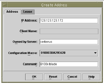
c. From the drop down selection list labeled Configuration Macro, select the name of the the client-specific macro that you set up in Step 6.
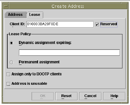
d. In the Create Address window, click the Lease tab (see FIGURE 10-10).
In the Client ID field, type the Client ID for the blade (that is, 01 followed by the blade's MAC address, with all alphabetic characters in uppercase, and without any colons; see "Invalid Cross-Reference Format"). Click OK.
8. If you are installing Solaris x86 onto a blade that previously ran Linux, proceed to Section 10.5, Re-initializing the Hard Disk On a Blade That Previously Ran Linux.
9. Proceed to Section 10.6, Configuring a Blade to Boot Temporarily From the Network.
10. Power on the Blade by following the instructions also in Section 10.6, Configuring a Blade to Boot Temporarily From the Network.
The Solaris x86 and Linux operating systems use different methods to lay out the disk partition table. Therefore when Solaris x86 first installs onto a blade that has previously been installed with Linux, it prompts you to run the fdisk utility to set up a Solaris disk partition table. This prompt requires user input and therefore causes a potential interruption to a Jumpstart installation. To avoid this problem, if you want to perform a completely automated custom Jumpstart on a B100x or B200x blade that has previously had Linux installed, you must first delete the partition table by using the command below. However, read the following caution before executing this command.
|
Caution - When you have deleted the disk partition table, any data stored on the hard disk is no longer accessible. Also, when you have done this, you can no longer boot Linux from the blade s hard disk. If you want to run Linux on the blade again, you must install it from the network by following the instructions in Chapter 4. |
You can automate this task within the Jumpstart configuration by using the fdisk keyword in the x86-class script. For more information, see Section 10.9, Preparatory Steps for Setting up a Jumpstart Installation for a Blade.
|
Note - To install Solaris x86 from a network install image onto a blade, you need to configure the blade temporarily to boot from the network. The System Controller command that you type in Step 2 below to configure the blade to do this is effective for 10 minutes. After that the blade's BIOS reverts to its previous booting behavior. Therefore, to cause the blade to boot from the network you must power it on within 10 minutes of running the bootmode command. (If the blade was already powered on when you ran the bootmode command, then to cause it to boot from the network you must reset the blade within 10 minutes. Follow the instructions below.) |
1. Log into the active System Controller by following the instructions in Chapter 2 of the Sun Fire B1600 Blade System Chassis Software Setup Guide if you are logging into a brand new chassis in its factory default state.
Otherwise log in using the user name and password assigned to you by your system administrator.
2. Type the following command at the System Controller's sc> prompt to cause the blade to boot from the network:
where n is the number of the slot containing the blade.
Alternatively, if you want to install the blade by using a differnet network interface, see Section 10.12, Installing Solaris x86 Onto a Blade by Using the Second, Third, or Fourth Network Interface.
3. Power on the blade by typing:
or, if the blade is already powered on, type:
where n is the number of the slot containing the blade.
4. Connect to the blade console by typing:
5. Proceed to Section 10.7, Monitoring the Network Booting Process and Starting the Solaris Installation.
|
Note - If you are performing an interactive installation, you must make sure that separate Boot and Solaris partitions are defined during the installation procedure. The way in which you need to do this depends upon the install media you are using and whether your blade is in its factory default state. Instructions for how to define the partitions correctly are provided in Section 10.8, Specifying Disk Partitioning During an Interactive Installation. |
When you have booted a blade (by following the instructions in Section 10.6, Configuring a Blade to Boot Temporarily From the Network), you can monitor the booting processes to check that no problems occur.
At the end of these booting processes, the server blade will prompt you to select the Solaris interactive installation or the Jumpstart installation.
1. Connect to the blade console by typing:
where n is the number of the slot containing the blade.
2. View the output displayed during the booting process:
After displaying the BIOS initialization screens, the blade will start to PXE boot from the network. At this point you will see the following information, which includes the MAC address that the blade is using for the boot process:
After a few seconds the blade will pick up the primary bootstrap program from the network install image and the following message will be displayed.
After a few more seconds the primary bootstrap will load and execute the secondary bootstrap program.
The following screen illustrates this point in the booting process:
After a few more seconds again a screen will appear prompting you to specify whether you want to perform a Solaris interactive or a Jumpstart installation.
3. Press 1 and press [RETURN] to perform the interactive installation.
When you have specified the type of installation you require, the blade begins to boot the Solaris operating system:
The interactive installation program then begins:
4. Select the language you require.
5. Proceed to section Section 10.8, Specifying Disk Partitioning During an Interactive Installation.
If you are performing an interactive installation of Solaris x86, you need to make sure that separate Boot and Solaris partitions are defined on the blade's hard disk. This enables the blade to identify its boot device correctly during reboots performed after the operating system has been installed from the network.
If you are performing a Jumpstart installation, skip this section. For blades that use Jumpstart, the boot device is set by the custom x86-finish script after the installation has completed and regardless of the disk partitions defined. For information about the x86-finish script, see Section 10.9, Preparatory Steps for Setting up a Jumpstart Installation for a Blade.
If you do not define separate Boot and Solaris partitions during an interactive installation, you may encounter the problem described in Chapter 14, Synopsis: Blade Boots to Device Configuration Assistant on Every Reboot After an Interactive Network Installation.
The actions you need to perform in this section depend on the install media (CDs or DVD) you have used to build the install image on your Network Install Server.
If you are installing Solaris x86 onto:
During a Webstart installation, select the 'Custom Install' option and specify separate Boot and Solaris partitions (see Section 10.8.7, Specifying Separate Boot and Solaris Partitions During a Manual Webstart Installation.
If you are installing Solaris x86 onto a blade in its factory default state, you will receive the following message from the Solaris installation utility:
2. In the screen for creating a Solaris fdisk partition, select "Use entire disk for Solaris and boot partitions (28615MB)".
4. Go to Section 10.8.8, Completing the Solaris x86 Installation.
If you are installing Solaris x86 onto a previously used blade whose disk partition table contains more than one disk partition, you will be prompted by the Solaris installation utility to decide whether to re-use the existing partition layout or to abort the installation utility:
 If you know that the existing disk partition table contains separate Solaris and Boot partitions, continue the installation process by pressing [F2], then go to Section 10.8.8, Completing the Solaris x86 Installation.
|
Note - For information about what happens if you press [F2] but the disk partition table contains separate Solaris and Boot partitions, see Chapter 14. |
If you are not certain that the disk partition table contains separate Solaris and Boot partitions, you need to cancel the installation, remove the entire disk partition table, and then run the Solaris installation program again.
1. Press [F5] to cancel the installation.
2. Follow the instructions in Section 10.8.6, Removing the Entire Disk Partition Table Before Restarting the Solaris Install Program.
If you are installing Solaris x86 onto a previously used blade whose disk partition table contains only a single partition (that is, it contains no separate Boot and Solaris partitions), you will not receive an error message to the effect that there is "No Solaris fdisk Partition" on the disk, or prompting you to use a particular partition.
|
Caution - If you arrive at the "Select Disks" screen and you have not received a disk partition error message or prompt, then you must abort the Solaris installation. |
2. Follow the instructions in Section 10.8.6, Removing the Entire Disk Partition Table Before Restarting the Solaris Install Program.
This section tells you how to remove an existing disk partition table on a blade so that Solaris will install onto it as if the blade is in its factory default state. You need to do this to prevent the blade from booting to the Device Configuration Assistant each time you reboot after performing an interactive network installation on a blade with a previously existing disk partition table.
|
Note - If you abort an interactive network installation on a blade, you will remain logged in as root. |
1. At the blade's console prompt, run the format command:
# format Searching for disks...done AVAILABLE DISK SELECTIONS: 0. c0d0 <DEFAULT cyl 58098 alt 2 hd 16 sec 63> /pci@0,0/pci-ide@1f,1/ide@0/cmdk@0,0 Specify disk (enter its number): 0 |
2. Type 0 (to specify the disk you want to format) and press [ENTER].
3. At the format> prompt, type:
4. Type 3 ("Delete a partition").
5. When prompted, specify the number of the partition to be deleted.
In the example in Step 3, the partition to be removed is number 1.
6. Type Y at the next prompt to delete the partition:
Are you sure you want to delete partition 1? This will make all files and programs in this partition inaccessible (type "y" or "n"). y |
7. Repeat Step 4 through Step 6 until there are no longer any partitions defined:
8. Type 4 to exit the fdisk utility, then type q to quit the format utility.
9. Now that the blade's hard disk has been restored to its factory default state, restart the Solaris installation procedure.
To do this, follow the instructions in Section 10.6, Configuring a Blade to Boot Temporarily From the Network, and then repeat Section 10.7, Monitoring the Network Booting Process and Starting the Solaris Installation.
This section is for network install images created from DVD media resulting in the Webstart Installation utility running. This utility manages the installation of the operating system onto the blade. Follow the instructions in this section to make sure the disk partitions on the blade are correctly defined to enable the blade to reboot after the operating system has installed from the network.
1. When prompted, type 2 to select the option to perform a 'Custom Install':
2. When prompted to lay out file systems on disk c0d0 (bootdisk), type y:
3. Follow the on-screen instructions to define partition 1 as the x86Boot partition with a size of 10MB, and partition 2 as the Solaris partition using the remaining free disk space.
When you have finished configuring the disk partitions you will see a screen summarising them. For example:
4. Press [ENTER] to go to the next screen, and complete the installation the custom installation.
There is no more platform-specific configuration required for the blades after this point. Proceed to Section 10.8.8, Completing the Solaris x86 Installation.
The procedures you have followed to create a blade-specific install image are complete. The remainder of this chapter contains information supplementary to these procedures.
For documentation describing the interactive or Webstart Solaris installations, refer to the Solaris 9 Installation Guide.
The previous sections of this chapter have explained how to configure the DHCP server and network install image so that the B100x and B200x blades can be installed interactively. An interactive installation requires a lot of user input and it is time-consuming to use this process when installing multiple blades.
This section provides the extra steps you need to perform to enable the blades to be installed in a completely hands-free manner. This is known as a Jumpstart installation and is fully documented in the Solaris 9 Installation Guide.
1. Log into the Network Install Server as root and create a directory to hold the Jumpstart configuration files.
The instructions in this section assume /export/jumpstart as the location of the Jumpstart configuration files.
2. Copy the sample jumpstart directory from the install image to your jumpstart directory.
where install_dir-path is the location of the install image.
3. Share the Jumpstart directory.
To make the rules file and profiles accessible to systems on the network, you need to share the /export/jumpstart directory. To enable sharing of this directory, add the following line to the /etc/dfs/dfstab file:
Then, at the command line, type:
4. Modify the file called rules to suit your site's requirements.
a. This file contains a lot of information. Comment out every line except the line starting with arch i386:
b. Add the keyword x86-finish to the end of the line starting with arch i386. This line will then look as follows:
The rules file dictates which systems will be installed by the Jumpstart configuration. For more information about its function, refer to the Solaris 9 Installation Guide.
5. Edit the file called x86-class so that it describes the type of installation you want the Jumpstart to perform.
The fdisk key word automates the deletion of any existing disk partition table on the hard disk that may have been created by a previous installation of Solaris x86 or Linux. For more information about defining the x86-class file and its associated key words, refer to the Solaris 9 Installation Guide.
6. Use a text editor to create an x86-finish script that will perform the required post-intallation steps.
This file is required to ensure that the blades will reboot correctly after the Jumpstart installation has been accomplished. The file must contain the information below:
The x86-finish script file is used for post-installation operations such as the synchronising of bootenv.rc. It is also used to ensure that the kdmconfig utility does not run on the first reboot.
7. Run the check command to verify the rules file and to create a rules.ok file.
# ./check Validating rules... Validating profile x86-class... The custom JumpStart configuration is ok. |
8. Use a text editor to create a sysidcfg file (or to modify the existing sysidcfg file) in the directory /export/jumpstart.
If you have already set up Jumpstart on your Network Install Server, the file will already exist. Otherwise you must create it.
This file contains responses to questions asked during the Jumpstart installation concerning, for example, time zone, terminal type, security, IPv6, time and date , system locale, and root password. The values for some of the keywords in this file will be specific to your local network configuration and its use of different services (for example, NIS).
|
Note - The root password that you need to specify in the sysidcfg is an encrypted one. You can find out a password's encrypted value (to insert into the sysidcfg) by setting up a user on a system and looking in that system's /etc/shadow file. The user password gets encrypted when a new user is added to a system by the System Administrator. In the sample sysidcfg file below (FIGURE 10-13), the password shown is new.hope. Choose a password that conforms to your local secure password policy. |
|
Note - For information about creating or editing this file, refer to the Solaris 9 Installation Guide. Note that the four parameters printed in bold in FIGURE 10-13 are specific to Solaris x86. |
9. Proceed to Section 10.10, Configuring a Jumpstart Installation.
If you are configuring a blade to perform a Jumpstart installation there are two extensions to the configuration steps in Section 10.4, Configuring the Install Server and the DHCP Server to Install Solaris x86 Onto Each Blade. The extra tasks at Step 2 and at Step 6.)
 In Step 2 (Section 10.4, Configuring the Install Server and the DHCP Server to Install Solaris x86 Onto Each Blade), when you run the add_install_client utility you must include the Jumpstart configuration options on the command line. For a sample command, see FIGURE 10-15.
The sample command illustrated in FIGURE 10-15 uses the -b boot option. For information about the arguments taken by this option and required for the Jumpstart process to work on a blade, see Section 10.13, The New add_install_client -b Option at the end of this chapter.
 In Step 6 (in Section 10.4, Configuring the Install Server and the DHCP Server to Install Solaris x86 Onto Each Blade), when you are configuring the client-specific DHCP macro for the blade, you must add values for the SjumpsCF and SsysidCF option strings.
When setting up multiple blades to install from the same network image you can save time by using the tips in this section.
Most of the arguments taken by the add_install_client utility will be the same for each blade; only a blade's MAC address will change. Therefore, you can invoke the utililty from a shell script (see FIGURE 10-12, FIGURE 10-16 and FIGURE 10-17). The example in FIGURE 10-12 assumes the script is stored in /export/s9x/Solaris_9/Tools and named add-blade-B100x. The example in FIGURE 10-17 assumes the same location for the script, and also assumes it is named add-blade-B200x.
|
Note - Remember that the boothpath is different for B100x and B200x blades and for different interfaces. Make sure the scripts you use apply to groups of blades of the same type and also groups of blades that use the same network interface. For information about using an interface other than the default one, see Section 10.12, Installing Solaris x86 Onto a Blade by Using the Second, Third, or Fourth Network Interface. |
When you use wrapper scripts, the command to set up the blade using the add_install_client utility becomes:
A sample command for a B200x blade is:
This section tells you how to use the DHCP Manager's Include and Duplicate facilities to speed up the creation of macros when you are installing multiple x86 blades in a chassis.
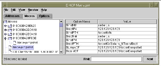
From FIGURE 10-1 and FIGURE 10-15 you can see that a number of the option strings you need to include in a blade's client-specific DHCP macro will be common to all blades that you install from the same network install image. For example in FIGURE 10-15 the following macros are the same for each client, regardless of the client blade's Ethernet address:
Install server (SinstNM): cerberus
Install server IP (SinstIP4): 123.123.123.163
Install server path (SinstPTH): /export/s9x
Root server name (SrootNM): cerberus
Root server IP (SrootIP4): 123.123.123.163
Root server path (SrootPTH): /export/s9x/Solaris_9/Tools/Boot
Profile location (SjumpsCF): 123.123.123.163:/export/jumpstart
sysidcfg location (SsysidCF): 123.123.123.163:/export/jumpstart
Conveniently the DHCP Manager GUI allows you to set up a named macro and then reference it from more than one client-specific macro by using an option string called 'Include'.
FIGURE 10-18 illustrates this by showing a macro called 'blade-jumpstart' that has been created to include by reference all the options associated with a Jumpstart installation. FIGURE 10-19 shows a client-specific macro that includes the 'blade-jumpstart' macro.
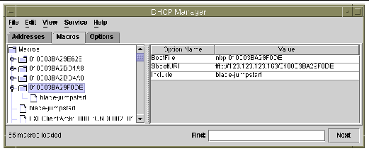
When you have set up a client-specific macro correctly for one blade, you can use the Duplicate option from the DHCP Manager's Edit menu, to create a new macro quickly for another blade. Only the Macro name and the contents of the SbootURI and BootFile options need to be changed for each blade.
This section describes how to use the DHCP command line tools to configure the required DHCP Manager macros instead of using the GUI.
 Create the global PXE macro by using the following DCHP table management command:
where ip-address is the IP address of the Network Install Server. (This command is the equivalent of performing the steps described in Section 10.3.2, Adding the Global PXE Macro for Solaris x86 to the DHCP Server.)
 Create the client-specific macro by using the DHCP table management commands appropriate to your blade. The commands below assume a blade with the properties described in FIGURE 10-7:
These commands are the equivalent of performing Step 6 in Section 10.4, Configuring the Install Server and the DHCP Server to Install Solaris x86 Onto Each Blade.
If you are performing a Jumpstart installation, you need to add the following two commands:
# dhtadm -M -m 010003BA29F0DE -e 'SjumpsCF=123.123.123.163:/export/jumpstart' # dhtadm -M -m 010003BA29F0DE -e 'SsysidCF=123.123.123.163:/export/jumpstart' |
 Assign an IP address to the blade:
where ip-address is the IP address of the blade, blade-hostname is the hostname of the blade, and network-address is the base address for the blade's subnet. This command is the equivalent of performing Step 7 in Section 10.4, Configuring the Install Server and the DHCP Server to Install Solaris x86 Onto Each Blade.
This section is for users who want to boot a blade by using a network interface other than the first interface. It provides information that you will need when you follow the instructions in Section 10.4, Configuring the Install Server and the DHCP Server to Install Solaris x86 Onto Each Blade
The B100x blades have two interfaces. The B200x blades have four. You need to give the DHCP and Network Install Servers different information about the MAC address and bootpath if you are not using the first network interface on the blade. Also you need to use a different argument to the System Controller's bootmode command, when you configure the blade temporarily to boot from the network.
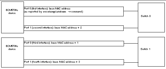
The B100x has one dual-port BCM5704s Gigabit Ethernet device. Each port on this device is connected to one of the Ethernet switches in the B1600 chassis. The BIOS takes responsibility for assigning the MAC addresses to the Ethernet ports as shown in FIGURE 10-20.

|
bootmode bootscript="boot net" sn[1] |
The B200x has two dual-port BCM5704s Gigabit Ethernet devices. Each port is connected to one of the Ethernet switches in the B1600 chassis. The BIOS takes responsibility for assigning the MAC addresses to the Ethernet ports as shown in FIGURE 10-21.
|
bootpath=/pci@0,0/pci8086,2545@3/pci8086,1460@1d/pci108e,16a8@3 |
|
|
bootmode bootscript="boot net" sn[2] |
|
bootpath=/pci@0,0/pci8086,2545@3/pci8086,1460@1f/pci108e,16a8@3 |
|
|
bootmode bootscript="boot snet1" sn[3] |
|
bootpath=/pci@0,0/pci8086,2545@3/pci8086,1460@1d/pci108e,16a8@3,1 |
|
|
bootmode bootscript="boot snet2" sn[4] |
|
bootpath=/pci@0,0/pci8086,2545@3/pci8086,1460@1f/pci108e,16a8@3,1 |
|
|
bootmode bootscript="boot snet3" sn[5] |
The add_install_client command in FIGURE 10-7 (see Section 10.4, Configuring the Install Server and the DHCP Server to Install Solaris x86 Onto Each Blade) uses a new -b option to set certain boot property values that need to be specified during the network PXE boot process for blade platforms.
These values are input-device, output-device, bootpath, and boot-args. This section describes their purpose:
Because the blades do not have a VGA screen or keyboard, the input-device and output-device must both be set to the serial console `ttya`. This ensures that the system console is re-directed to the blade's serial port, enabling you to interact with the blade through the console.
This property specifies the boot device for the blade. It removes the need for the Device Configuration Assistant to pause the system during booting to request you to select a boot device. Note that the bootpath value is platform-specific. For the correct values, see TABLE 10-1, TABLE 10-2, TABLE 10-3, TABLE 10-4, and TABLE 10-5.
This property holds a string of arguments that will be passed to the boot subsystem. In FIGURE 10-10 we use the property to esnure that a Jumpstart installation is performed when the blade PXE boots from the network. For more information, refer to boot(1M), kadb(1M), and kernel(1M).
Copyright © 2004, Sun Microsystems, Inc. All rights reserved.