| Sun Fire V890 Dynamic Reconfiguration User's Guide
|
    |
Using Dynamic Reconfiguration
|
This chapter provides detailed instructions for Dynamic Reconfiguration procedures on a Sun Fire V890 system. Topics covered in this chapter include:
How to Display Card Status
You can use the cfgadm command to display status information about cards and slots. Refer to the cfgadm(1M) man page for options to this command.
Accessing the Basic Status Display
Many DR operations require that you specify a card or slot.
 To obtain the system names for cards or slots, as superuser, type:
When used without options, the cfgadm command displays information about all known cards and slots. The following display shows a typical output.
# cfgadm
Ap_Id Type Receptacle Occupant Condition
PCI0 unknown empty unconfigured unknown
PCI1 unknown empty unconfigured unknown
PCI2 unknown empty unconfigured unknown
PCI3 mult/hp connected configured ok
PCI4 ethernet/hp connected configured ok
PCI5 pci-pci/hp connected configured ok
PCI6 unknown empty unconfigured unknown
PCI7 unknown empty unconfigured unknown
PCI8 unknown empty unconfigured unknown
SBa cpu/mem connected configured ok
SBb cpu/mem connected configured ok
SBc cpu/mem connected configured ok
SBd none empty unconfigured ok
|
The first column, Ap_Id, lists the system's attachment points. An attachment point is a collective term for a card and its associated slot. There are two types of system names for attachment points.
- A physical attachment point describes the physical path to the slot in the system device tree.
- A logical attachment point, or attachment point ID, is an alias created by the system to refer to the physical attachment point.
For example, in the cfgadm output shown previously, the logical attachment point ID of the PCI card in the first slot is PCI0.
|
Note - The cfgadm status display shows attachment points for both PCI cards and CPU/Memory boards. However, DR operations for Sun Fire V890 CPU/Memory boards are not supported.
|
The following table lists the attachment point IDs for all of the Sun Fire V890 PCI slots.
|
Slot
|
Attachment Point ID
|
|
PCI slot 0
|
PCI0
|
|
PCI slot 1
|
PCI1
|
|
PCI slot 2
|
PCI2
|
|
PCI slot 3
|
PCI3
|
|
PCI slot 4
|
PCI4
|
|
PCI slot 5
|
PCI5
|
|
PCI slot 6
|
PCI6
|
|
PCI slot 7
|
PCI7
|
|
PCI slot 8
|
PCI8
|
The following table describes the values that may appear in the Type, Receptacle, Occupant, and Condition columns of the basic status display. The values listed for the Type column represent the most common board and card types.
|
Column
|
Entry
|
Meaning
|
|
Type
|
mult/hp
|
Multifunction (hot-pluggable PCI card)
|
|
|
ethernet/hp
|
Gigabit Ethernet (hot-pluggable PCI card)
|
|
|
pci_pci/hp
|
Quad Ethernet (hot-pluggable PCI card)
|
|
|
scsi/hp
|
SCSI (hot-pluggable PCI card)
|
|
|
raid/hp
|
Hardware RAID (hot-pluggable PCI card)
|
|
|
tokenrg/hp
|
Token Ring (hot-pluggable PCI card)
|
|
|
fddi/hp
|
FDDI (hot-pluggable PCI card)
|
|
|
atm/hp
|
ATM (hot-pluggable PCI card)
|
|
|
network/hp
|
Network interface (unspecified type, hot-pluggable PCI card)
|
|
|
storage/hp
|
Storage interface (unspecified type, hot-pluggable PCI card)
|
|
|
display/hp
|
Graphics interface (unspecified type, hot-pluggable PCI card)
|
|
|
pci-card/hp
|
PCI card (unspecified type, hot-pluggable PCI card)
|
|
|
unknown
|
Board or card type cannot be determined
|
|
|
cpu/mem
|
CPU/Memory board
|
|
Receptacle
|
empty
|
Slot is empty
|
|
connected
|
Slot is electrically connected
|
|
disconnected
|
Slot is not electrically connected
|
|
Occupant
|
configured
|
Board or card is logically attached to the operating system
|
|
unconfigured
|
Board or card is logically detached from the operating system
|
|
Condition
|
ok
|
Board or card is ready for use
|
|
unknown
|
Board or card condition cannot be determined
|
|
failing
|
A board or card that was in the OK condition has developed a problem
|
|
failed
|
Board or card has failed
|
|
unusable
|
Either an attachment point has incompatible hardware or an empty attachment point lacks power or precharge current
|
Accessing the Detailed Status Display
You can use the -v (verbose) option to access expanded descriptions.
For a more detailed status report, as superuser, type:
In addition to the information provided by the basic status display, the detailed status information includes the physical attachment point of each card.
The following is an example of the display produced by the cfgadm -v command.
# cfgadm -v
Ap_Id Receptacle Occupant Condition Information When Type Busy Phys_Id
PCI0 empty unconfigured ok pci8b:5 Slot 0 Dec 31 19:05 unknown n /devices/pci@8,700000:hpc1_slot0
PCI1 empty unconfigured ok pci8b:4 Slot 1 Dec 31 19:05 unknown n /devices/pci@8,700000:hpc1_slot1
PCI2 empty unconfigured ok pci8b:3 Slot 2 Dec 31 19:05 unknown n /devices/pci@8,700000:hpc1_slot2
PCI3 connected configured ok pci8b:2 Slot 3 Dec 31 19:05 mult/hp n /devices/pci@8,700000:hpc1_slot3
PCI4 connected configured ok pci9b:4 Slot 4 Dec 31 19:05 ethernet/hp n /devices/pci@9,700000:hpc2_slot4
PCI5 connected configured ok pci9b:3 Slot 5 Dec 31 19:05 pci-pci/hp n /devices/pci@9,700000:hpc2_slot5
PCI6 empty unconfigured ok pci9b:2 Slot 6 Dec 31 19:05 unknown n /devices/pci@9,700000:hpc2_slot6
PCI7 empty unconfigured ok pci9a:1 Slot 7 Dec 31 19:05 unknown n /devices/pci@9,600000:hpc0_slot7
PCI8 empty unconfigured ok pci9a:2 Slot 8 Dec 31 19:05 unknown n /devices/pci@9,600000:hpc0_slot8
SBa connected unconfigured ok powered-on, assigned Dec 31 19:05 cpu/mem n /devices/pseudo/gptwo@0:SBa
SBb connected configured ok powered-on, assigned Dec 31 19:05 cpu/mem n /devices/pseudo/gptwo@0:SBb
SBc connected configured ok powered-on, assigned Dec 31 19:05 cpu/mem n /devices/pseudo/gptwo@0:SBc
SBd empty unconfigured ok assigned Dec 31 19:05 none n /devices/pseudo/gptwo@0:SBd
|
About the Status LEDs
Inside the Sun Fire V890 system, status LEDs provide power, fault, and hot-plug indications for each PCI card slot. Each LED is labeled with an icon as shown below:
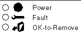
The following tables summarize how to interpret the LEDs for various hot-plug scenarios. In each table, the LED states are represented as follows:
TABLE 2-1 Removing a Card

|
Action
|
|
Description
|
|
1
|

|
Slot occupied; Power LED on; card is logically connected
|
|
2
|

|
Start hot-plug removal via push button or cfgadm command
|
|
3
|

|
Fault LED blinks during unconfigure operation
|
|
4
|

|
Operation successful; OK-to-Remove LED turns on
|
|
5
|

|
Remove card; OK-to-Remove LED turns off
|
TABLE 2-2 Removing a Card - Card Busy
|
Action
|

|
Description
|
|
1
|

|
Slot occupied; Power LED on
|
|
2
|

|
Start hot-plug removal via push button or cfgadm command
|
|
3
|

|
Fault LED blinks briefly during unconfigure operation
|
|
4
|

|
Card busy; check system console messages
|
TABLE 2-3 Adding a Card
|
Action
|

|
Description
|
|
1
|

|
Slot empty; all LEDs off
|
|
2
|

|
Insert new card; OK-to-Remove LED turns on upon insertion
|
|
3
|

|
Start hot-plug addition via push button or cfgadm command
|
|
4
|

|
Power LED lights; Fault LED blinks during configure operation
|
|
5
|

|
Operation successful; Power LED remains on
|
TABLE 2-4 Adding a Card - Fault Encountered
|
Action
|

|
Description
|
|
1
|

|
Slot empty; all LEDs off
|
|
2
|

|
Insert new card; OK-to-Remove LED turns on upon insertion
|
|
3
|

|
Start hot-plug addition via push button or cfgadm command
|
|
4
|

|
Fault LED blinks during configure operation
|
|
5
|

|
Fault encountered; Fault LED turns on
|
|
6
|

|
Remove faulty card
|
|
7
|

|
Slot empty; all LEDs off
|
How to Identify Cards and Slots
|
Note - Internal access to the Sun Fire V890 system is restricted to qualified service personnel. Installation procedures for internal components are covered in the Sun Fire V890 Server Service Manual, which is included on the Sun Fire V890 Server Online Documentation CD.
|

|
Caution - Hazardous energy levels are present inside the system when the system remains connected to a power source, regardless of the keyswitch position. Also, hazardous energy levels are present in the system's batteries even when all AC power cords are disconnected. Follow the safety procedures in your system Owner's Guide or Service Manual.
|

|
Caution - Avoid keeping doors open for extended periods of time while the system is operating. All doors must be closed to prevent automatic thermal shutdown.
|
Identifying a Card Inside the System
1. Check the system front panel LEDs.
If a card is faulty, a directional LED on the front panel display turns on and points to the side of the system where the card is located. If a card is ready for you to remove after a successful DR operation, the OK-to-Remove LED turns on and a directional LED indicates the location of the card. For additional details on the system front panel LEDs, see the Sun Fire V890 Server Owner's Guide.
2. Open the appropriate side access door and check the interior status LEDs.
Inside the system, a Fault LED turns on to indicate which slot contains the faulty card. After a successful DR remove operation, an OK-to-Remove LED turns on to indicate which slot contains the card to be removed. For more information, see About the Status LEDs.
Identifying a Card or Slot From a System Console
1. Log in to the system as superuser.
2. Type the cfgadm command to display detailed status information for the system's PCI slots.
The command output identifies each slot and any cards occupying those slots. For more information, see How to Display Card Status.
3. Determine the attachment point ID for the card to be removed, or the slot where you will add the new card.
To identify a faulty card, look in the Condition column of the cfgadm output for cards marked failed, failing, or unusable. The Ap_Id column indicates the slot's attachment point ID.
How to Prepare a PCI Card for RemovalWhat to Do
1. Terminate usage of all devices on the card.
All I/O devices must be closed before they can be unconfigured. Ensure that any networking interfaces on the card are not in use. All storage devices attached to the card must be unmounted and closed.
- To identify the components that are on the card to be unconfigured, use the prtdiag(1M), ifconfig(1M), mount(1M), df(1), ps(1), or swap(1M) commands.
- To see which processes have these devices open, use the fuser(1M) command.

- Warn all users to stop using the functions that the card provides.
2. Use the ifconfig command to terminate usage of any network interfaces on the card.
|
Note - You cannot terminate the usage of network interfaces if the network interface is the primary network interface and no alternate path is available.
|
3. If any disk partitions that the card controls are used for swap space, remove them from the swap configuration.
4. Use the umount(1M) command to unmount any file systems, including Solstice DiskSuite metadevices, residing on disk partitions controlled by the card.
|
Note - Use the lockfs command to place a hard lock on the file systems before unmounting them.
|

|
Caution - Unmounting file systems may affect NFS client systems.
|
5. Remove any Solstice DiskSuite databases from disk partitions that the card controls.
The location of Solstice DiskSuite databases is chosen by the system user and can be changed.
6. For any process that directly opens a device or raw partition that the card controls, either kill the process using the kill command, or direct the process to close the open device on the card.
7. If a detach-unsafe device is present on the card, close all instances of the device and use modunload(1M) to unload the driver.
See How to Remove PCI Cards That Use Detach-Unsafe Drivers
What Next
To remove a PCI card, see How to Remove a PCI Card.
How to Remove a PCI Card
|
Note - Internal access to the Sun Fire V890 system is restricted to qualified service personnel. Installation procedures for internal components are covered in the Sun Fire V890 Server Service Manual, which is included on the Sun Fire V890 Server Online Documentation CD.
|

|
Caution - Hazardous energy levels are present inside the system when the system remains connected to a power source, regardless of the keyswitch position. Also, hazardous energy levels are present in the system's batteries even when all AC power cords are disconnected. Be sure to follow the safety procedures in your system Owner's Guide or Service Manual.
|

|
Caution - Avoid keeping doors open for extended periods of time while the system is operating. All doors must be closed to prevent automatic thermal shutdown.
|
Before You Begin
What to Do
1. A qualified service professional should open the appropriate side access door.
See "How to Open the Side Access Doors" in the Sun Fire V890 Server Owner's Guide.
If you are replacing a faulty card a Fault LED inside the system illuminates to indicate which slot contains the faulty card. See About the Status LEDs.
2. Use a hot-plug push button or the cfgadm command to initiate the hot-plug operation.
- If you are working near the system, press the push button for the slot that contains the card to be removed.
- If you are working at a system console, enter the following cfgadm command and the attachment point ID for the card to be removed:
# cfgadm -c disconnect ap_id
|
|
Note - You can also initiate hot-plug operations through a graphical user interface using a version of Sun Management Center software that supports DR operations. For more information, refer to the Sun Management Center Software User's Guide and the Sun Management Center Software Supplement for High-End Entry Servers (Workgroup Servers).
|
The Fault LED for the slot blinks while the card is being unconfigured.
3. When the OK-to-Remove LED illuminates, remove the card from its slot.

|
Caution - Do not remove a card until the OK-to-Remove LED illuminates; otherwise, the system will crash.
|
Refer to the Sun Fire V890 Server Service Manual for removal and replacement procedures. If the OK-to-Remove LED never turns on, the process has failed.
If a replacement card is not immediately available, you can leave the failed card in the system until a replacement arrives.
|
Note - After a card is removed, the DR software automatically executes the Solaris devfsadm command. The devfsadm command updates the /etc/path_to_inst file to remove any physical path names for devices associated with the card. The same path names are removed from the /devices hierarchy and associated links are removed from the /dev directory.
|
4. If you unloaded any detach-unsafe drivers before removing a PCI card, reload any drivers that are required by other devices in the system.
What Next
To add a new PCI card, see How to Add a PCI Card.
How to Remove PCI Cards That Use Detach-Unsafe Drivers
Some drivers do not yet support DR on Sun Fire V890 systems. DR cannot detach these drivers, but you can remove some undetachable drivers manually using the following procedure.
What to Do
1. Stop usage of all detach-unsafe devices on the card to be removed.
2. Stop usage of all other devices of the same type used throughout the entire system.
The system can use these devices after the DR unconfigure operation is complete.
3. Use the appropriate UNIX commands to manually close all instances of the affected drivers.
4. Use the modinfo(1M) command to find the module IDs of the drivers, then use the modunload(1M) command to unload them.
|
Note - Many third-party drivers (those purchased from vendors other than Sun Microsystems) do not support the standard Solaris modunload(1M) interface. Conditions that invoke the driver functions occur infrequently during normal operation, and these functions may sometimes be missing or work improperly. Sun Microsystems suggests that you test these driver functions on a development system during the qualification and installation phases of any third-party device.
|
What Next
To remove a PCI card, see How to Remove a PCI Card.
How to Add a PCI Card
|
Note - Internal access to the Sun Fire V890 system is restricted to qualified service personnel. Installation procedures for internal components are covered in the Sun Fire V890 Server Service Manual, which is included on the Sun Fire V890 Server Online Documentation CD.
|

|
Caution - Hazardous energy levels are present inside the system when the system remains connected to a power source, regardless of the keyswitch position. Also, hazardous energy levels are present in the system's batteries even when all AC power cords are disconnected. Be sure to follow the safety procedures in your system Owner's Guide or Service Manual.
|

|
Caution - Avoid keeping doors open for extended periods of time while the system is operating. All doors must be closed to prevent automatic thermal shutdown.
|
Before You Begin

|
Caution - Inserting a faulty card may cause a system crash. Use only cards that are known to function properly.
|
What to Do
1. Verify that the selected slot is ready to receive the new card.
- If you are working inside the system, confirm that all three LEDs for the slot are off.
- If you are working at a system console, use the cfgadm command to verify that the slot is ready. See How to Display Card Status.
Confirm in the cfgadm output that the selected slot's status in the Receptacle column is empty or disconnected and that in the Occupant column it shows unconfigured.
2. Physically install the card into the slot.
Refer to the Sun Fire V890 Server Service Manual for removal and replacement procedures.
3. Connect any cables or interface modules to the card.
4. Use a hot-plug push button or the cfgadm command to initiate the hot-plug operation.
If you are working near the system, press the push button for the slot that contains the new card.
If you are working at a console, enter the following cfgadm command and the attachment point ID for the selected slot:
# cfgadm -c configure ap_id
|
|
Note - You can also initiate hot-plug operations through a graphical user interface using a version of Sun Management Center software that supports DR operations. For more information, refer to the Sun Management Center Software User's Guide and the Sun Management Center Software Supplement for High-End Entry Servers (Workgroup Servers).
|
The Fault LED for the slot blinks while the card is being configured. When the Fault LED stops blinking, the process is complete. If the Fault LED turns on instead, the process has failed.
|
Note - If the process fails, the slot is automatically powered off. In order to power up the slot and execute the card's on-board diagnostics, you must first use the -x poweron option of the cfgadm command.
|
|
Note - After a card is added, the DR software automatically executes the Solaris devfsadm command to reconfigure all of the card's devices. The devfsadm command updates the /etc/path_to_inst file with physical path names for the new devices. The same path names are added to the /devices hierarchy and appropriate links are created in the /dev directory.
|
5. Perform any final configuration steps as needed.
a. Activate the devices on the card using the mount and ifconfig commands, as appropriate.
b. Restore or create any desired swap partitions.
c. Restore or create any desired multipathing and/or volume management configurations.
| Sun Fire V890 Dynamic Reconfiguration User's Guide
|
817-4166-10
|
|
Copyright © 2004, Sun Microsystems, Inc. All rights reserved.