| C H A P T E R 4 |
|
Powering Up and Configuring the Server |
This chapter explains how to use the Power On switch to apply power to the server, boot to the operating system, use the serial console, update system software, and validate the operation of the Sun Fire V60x and Sun Fire V65x servers. The chapter contains these sections:
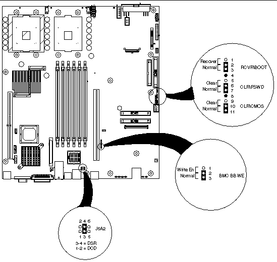
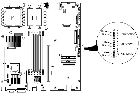
Part of configuring the server involves setting the jumper positions on the main board. The jumper locations are shown in FIGURE 4-1 and summarized in TABLE 4-1.
|
Configures either a DSR or a DCD signal to the connector. See Rear Panel RJ-45 Serial COM2 Connector and Setting the Serial COM2 Port Jumper. |
||
|
If these pins are jumpered, the CMOS settings are cleared. These pins should not be jumpered for normal operation. |
||
|
If these pins are jumpered, the password is cleared. These pins should not be jumpered for normal operation. |
||
|
If these pins are jumpered, the system will attempt BIOS recovery. These pins should not be jumpered for normal operation. |
||
|
If these pins are jumpered, BMC boot block is erasable and programmable at next reset. These pins should not be jumpered for normal operation. |
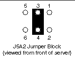
A serial port jumper on the Main Board is preset by default to the position that satisfies most serial port configurations. The jumper is located at the rear of the server, on the Main Board, next to the rear RJ-45 serial connector. The jumper is on the jumper block labeled J5A2. The top cover of the server must be removed to access the jumper.
For serial devices that require a DSR signal (default), the J5A2 jumper block must be configured as follows: place the jumper across positions 3 and 4 (the two middle jumper posts) as shown in FIGURE 4-2.
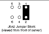
For serial devices that require a DCD signal, the J5A2 jumper block must be configured as follows: place the jumper across positions 1 and 2 as shown in FIGURE 4-3.

|
Caution - The power switch on the front of the server is an On/Off switch, but it does not isolate the equipment from the AC power being supplied through the AC power cord. |
The location of the switch is shown in FIGURE 4-4.
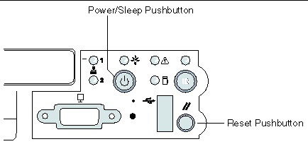
Pushing the power pushbutton sends a signal to monitoring circuitry inside the server. The switch does not directly control high-voltage AC; it controls only low-voltage signals. When the monitoring circuitry detects that the button has been depressed, it activates the power supply and powers up the server. Likewise, when the server is powered up, pushing the switch powers the server down.
The main method for isolating the server from all high voltage is to physically remove the AC power cord. If the power cord is not removed, the only other way to isolate the server from high voltage is to open all external circuit breakers that supply AC voltage to the equipment.
It may be necessary to clear CMOS memory in order to restore the default BIOS passwords required to boot the server (user) or access setup functions (supervisor), as well as the default BIOS settings.
The CMOS configuration RAM may be reset by one of two methods:
The CMOS can also be set to a default setting through the BIOS Setup. It will automatically be reset if it becomes corrupted.
Follow these steps to clear the CMOS using the buttons on the front panel:
1. Power off the system, but leave the AC power connected so the 5V standby is available.
2. Verify that the Clear CMOS jumper is in the "not clear" position.
3. Hold down the reset button for at least 4 seconds.
4. While the reset button is still depressed, press the power on/off button and hold for at least 2 seconds.
5. Simultaneously release both the power on/off and reset buttons.
Upon completion of these steps, the BMC asserts the clear CMOS signal to emulate the movement of the Clear CMOS jumper. The BIOS clears CMOS as if you had moved the Clear CMOS jumper on the main board. CMOS is cleared only once per front panel button sequence. The BMC releases the CMOS clear line during the next system reset. Removing the Clear CMOS jumper from the main board can disable the Front Panel CMOS reset function. In addition, the jumper should be retained in case the CMOS needs to be cleared using the baseboard header.
Follow these steps to clear the CMOS using the CLR\CMOS jumper on the main board (see FIGURE 4-5):
1. Power off the system, but leave the AC power connected so the 5V standby is available.
2. Verify that the CLR\CMOS jumper is in the "Clear" position.
3. Press the power on/off button.
When the BIOS detects a reset CMOS request (either through the front panel or with the Clear CMOS jumper), CMOS defaults are loaded during the next POST sequence. Note that non-volatile storage for embedded devices may or may not be affected by the clear CMOS operation depending on the available hardware support.
4. Place the CLR\CMOS jumper in the "Normal" position.
As soon as power is applied to the server, the bootup process begins. Boot messages are sent to either a monitor attached to the video port, or to a serial console attached to the rear RJ-45 serial COM2 port.
The server is configured by default to initially send BIOS and kernel messages to both the serial port and the video port. However, when the boot process reaches the OS load point, the messages and screens are sent only to the video port. After bootup is finished, the configuration can be changed to send all messages to the serial console (see Configuring an External Serial Console).
|
Note - The USB ports may be disabled until the OS is booted and the USB drivers are installed. A PS/2 keyboard is required if a keyboard is necessary for initial bootup and configuration. |
The first bootup screen is shown in FIGURE 4-6.
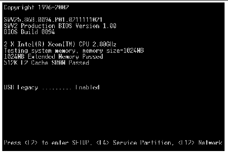
At the bottom of the screen, you are given the option to press the following function keys:
Press F2 to enter the BIOS Setup Utility. The main BIOS Setup Utility screen shown in FIGURE 4-7 appears.
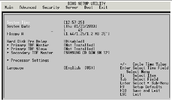

|
Caution - Changing the BIOS settings may cause undesirable effects, and in some cases may disable the server. Be very careful before changing the BIOS configuration. |
It is important to note the default boot sequence. The boot sequence is accessed by using the right arrow key to select the Boot menu item on the top of the BIOS screen, then pressing Enter. The boot sequence is then displayed. The default boot sequence is as shown in FIGURE 4-8.
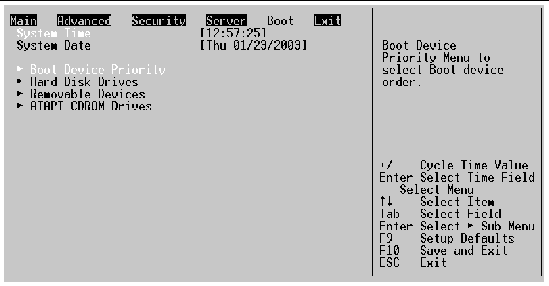 [ D ]
[ D ]
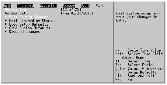
You can always restore all of the default BIOS settings by scrolling to the Exit menu item along the top of the screen. The BIOS Setup screen then appears as shown in FIGURE 4-9.
 [ D ]
[ D ]
To restore all of the default settings, scroll to "Load Setup Defaults" and press Enter, then select Yes at the prompt and press Enter again. Now press F10 to save the settings and exit.
When you exit the BIOS setup utility, the bootup process continues.
|
Note - To update the server BIOS, see Updating the Server Configuration. |
|
Note - If you have a Sun Fire V60x server or Sun Fire V65x server with the Solaris operating environment preinstalled, the Service Partition is also preinstalled. If your server does not have a preinstalled operating system, the Service Partition is not installed. The Service Partition can be installed as described in Service Partition. |
The Service Partition is a special partition that contains utilities used to manage and configure the Server. If the Service Partition is installed, press <F4> during bootup to display the Service Partition Menu (see FIGURE 4-32). If the Service Partition is not installed, you can install it, or you can also run the utilities directly from the Sun Diagnostics CD. Refer to Service Partition for information on installing or restoring the Service Partition, or running the utilities from the Sun Diagnostics CD.
|
Note - The operations performed with the service partition menus can also be executed from the Sun Fire V60x and Sun Fire V65x servers Diagnostic CD. See Using the Sun Diagnostics CD. |
When you are finished using the service partition, you must depress the Ctrl-Alt-Delete keys simultaneously to reboot.
If you press F12 to boot from the network, the server software looks for a valid boot file name on the network. If it finds such a file name, it boots from the network. If it cannot find a valid file name, it gives up and continues to boot from the hard disk. FIGURE 4-10 is an example of how the screen appears when booting from the network fails.

Pre-boot Execution Environment (PXE) is a method by which the server can be booted from a remote server. This allows the system to boot without any knowledge of the Operating System on the server. The PXE environment uses DHCP to obtain network addresses. PXE is primarily used for loading operating systems, configuring the system, or burn-in type testing. PXE booting will only work if a properly configured PXE server is available.
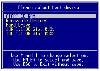
Press the Esc key to go to the boot device selection menu. This menu, shown in FIGURE 4-11, allows you to select the device from which the system will boot. To select a boot device, scroll to the desired device and press Enter; otherwise, press Esc to exit without changing the boot device.
|
Note - When you select a boot device with the menu shown in FIGURE 4-11, it only affects the current boot. Subsequent boots revert to the device access sequence stored in the BIOS default settings. |
During the boot process, you will be presented with the choices described in the following sections. Type "N" to keep the current information, "Y" to change the information.
Ethernet ports may take a short amount of time (less than 1second) to activate after ifconfig brings them up. This has been noted when the Server is running Red Hat Linux v7.2 or v7.3.
Some USB-connected CD-ROM devices perform unreliably on the Sun Fire V60x server and Sun Fire V65x server. Use the internal CD-ROM device when possible.
The external SCSI bus is scanned for disk devices before the internal bus is scanned. As a result, Linux will label external drives before internal drives. Exercise caution when adding and removing external devices because operating system drive device names may change, leaving the system unable to boot because the external SCSI device may not be a boot drive.
A PS/2 pointing device (mouse) may be misidentified during OS installation. To correct the mouse configuration for the Linux OS, run the "setup" tool from the command line. Select the "Mouse configuration" option then identify the connected pointing device. Save the change and exit the setup utility. The Solaris OS automatically detects the mouse, and if it finds that it needs to change some information, it starts the kdmconfig on reboot.
The bootup process eventually takes you to the point where the operating system loads.
In all cases, the serial port on the rear panel is operational and you can redirect boot messages to an external console. See Configuring an External Serial Console for details.
The Sun Fire V60x and Sun Fire V65x servers feature Hyper-threadingtm capable processors. Enabling Hyper-threading causes each physical CPU to act as two logical CPUs. Enabling Hyper-threading on a dual processor Sun Fire V60x server or Sun Fire V65x server causes the operating system to recognize four distinct processors.
|
Note - Hyper-threading is disabled, by default, when the Sun Fire V60x and Sun Fire V65x servers are shipped. |
Hyper-threading may be enabled or disabled in the system BIOS configuration menu by using the following instructions:
1. Press the F2 key during the power-on self test (POST) while the server is booting to enter the BIOS configuration menu.
2. Using the down arrow key, scroll to "Processor Settings" then press the enter key.
3. Toggle the feature "Hyper-threading using the enter and arrow keys.
4. Press the Esc key once to exit the "Processor Settings" menu.
5. Press the left arrow key to highlight the "Exit" menu.
6. Press the Enter key to select "Exit Saving Changes".
7. Press the Enter key again to confirm the new BIOS setting.
In most high-performance computing (HPC) environments, it is best to disable the Hyper-threading feature. In some mixed-task compute environments Hyper-threading can improve performance. One example of a mixed-task environment is a web and media server that simultaneously runs HTTP daemons and floating point media encoders.
If Hyper-threading is enabled some benchmarks may report inconsistent results due to the chaotic nature of process scheduling on asymmetric logical processors.
The RJ-45 serial COM2 port on the Sun Fire V60x and Sun Fire V65x servers rear panel (see FIGURE 4-12) can be used to direct boot messages to a serial console (for example, a laptop running HyperTerminal).

The server is initially configured to send all the initial BIOS and kernel bootup messages to both the serial console and the VGA port. Use the information in this section only if you need to restore or change the configuration.
The default communications settings for serial COM2 port on the rear panel of the server are:
You can connect to the serial COM2 port if you have an adapter cable that has an
RJ-45 connector at one end and a DB9 connector at the other, wired in accordance with See Back Serial COM2 Port Adapter Pinout. You can then connect the COM1 port of a PC or laptop to the serial COM2 port using the adapter cable and use HyperTerminal (or a similar application) to communicate with the server.
An ANSI 500 terminal emulator is needed to have the display appear properly during BIOS setup and when using the Sun Fire V60x and Sun Fire V65x servers Diagnostics CD or Service Partition tools.
To set up the server to direct messages to an external serial console:
1. On bootup, press F2 to select BIOS setup
2. Select the Security menu on the BIOS Setup Utility window
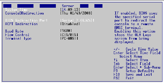
4. Select the options as shown in FIGURE 4-13.
 [ D ]
[ D ]
5. Press Esc to go back to the main BIOS setup menu.
6. Exit the BIOS setup utility saving the changes you have made.
The boot messages are now directed to your external serial console. In this example, the BIOS setup allows the messages to be directed to COM1 of an external PC running HyperTerminal.
The intended usage model for the RJ-45 serial connector on the back of the server is for use as an interface to a serial port concentrator, allowing for remote access to the server's Emergency Management Port (EMP).
When redirecting the console through a modem, as opposed to a null modem cable, the modem needs to be configured with the following:
|
Note - By default, the Sun Fire V60x and Sun Fire V65x servers are shipped without the Service Partition installed. It can be installed as described in Service Partition. |
If the Service Partition is installed, when you press F4 at the initial bootup screen, the Service Partition Menu appears (see FIGURE 4-14).
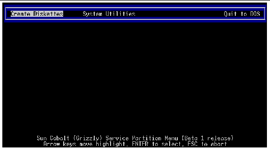
There are three main menu items across the top of this screen:
Pressing Enter with the Create Diskettes menu item highlighted brings up a submenu that lists the various diskettes you can create (see FIGURE 4-15).
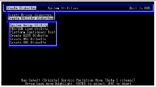
You can use this submenu to create various types of standalone diskettes that you can use to boot servers and run particular tests, utilities, or Flash the BIOS, independently of using the service partition System Utilities menu.
The following disks can be created:
Pressing Enter with the System Utilities menu item highlighted brings up the submenu shown in FIGURE 4-16.
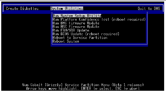
The following submenu items are available:
If installed, the Service Partition on the hard disk of the Sun Fire V60x and Sun Fire V65x servers allows you to perform server management, configuration and validation testing. To bring up the service partition, reboot and press the <F4> function key when the first BIOS screen appears.
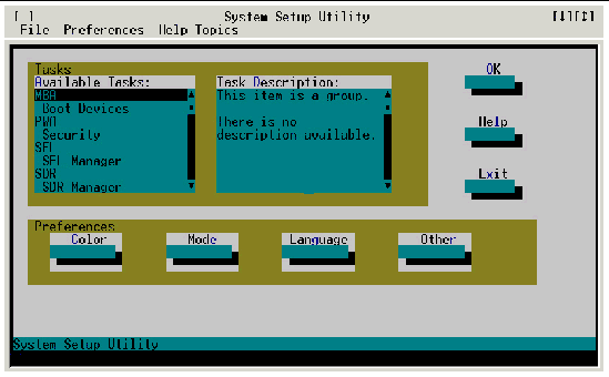
Select Run System Setup Utility to run system setup. The System Setup Utility main window appears (see FIGURE 4-17).
 [ D ]
[ D ]
The System Setup Utility (SSU) allows you to configure the following:
Because the server supports running the SSU over a serial console, all of the menus work in text mode only.
The Multiboot Add-in (MBA) feature of the SSU allows you to select the boot order for all bootable peripheral devices. To select the boot device priority, double-click the MBA Boot Devices menu item in the Available Tasks pane of the SSU main window. The Multiboot Options Add-in window appears (see FIGURE 4-18).
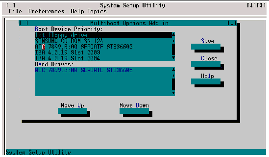
To change boot priorities, select a boot device and use the Move Down and Move Up buttons to move the device boot priority.
|
Note - This menu allows you to change the boot order without going into the BIOS setup. |
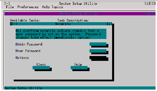
The Password Authorization feature of the SSU allow you to set BIOS passwords and other security options. To configure server security, double-click the PWA Security menu item in the Available Tasks pane of the SSU main window. The main Security window appears (see FIGURE 4-19).
|
Note - This menu allows you to change the security settings without going into the BIOS setup. |
 [ D ]
[ D ]
Use the Admin Password, User Password, and Options buttons to configure the security options.
The System Setup Utility (SSU) allows you to manage the following:
The server maintains a system event log (SEL) in non-volatile memory, which holds approximately 3200 SEL entries. The log can be viewed and cleared using the SSU. To manage the log, double-click the SEL Manager menu item on the Available Tasks pane of the main SSU window. The System Event Log appears, and you can use the menu bar at the top of the log window to save the log, open a log, clear the log, or reload the log.
The SEL can also be cleared if you select BIOS setup during bootup (choose <F2>) and go into the Server menu. Choose Event Log Configuration > Clear All Event Logs > Yes. Press the Esc key until you receive the prompt to exit setup. If you choose to save your changes, the System Event Log will be cleared the next time you boot.
In addition, the SEL is cleared automatically each time you run the Platform Confidence Test (PCT). See Run Platform Confidence Test (PCT) for more details on the PCT.
The Sensor Data Record (SDR) Manager allows you to view the current sensor data for the system, save the SDR data to a file, and view SDR information previously saved to a file. The SDR data is saved in standard SDR format. To manage the SDR data, double-click the SDR Manager menu item on the Available Tasks pane of the main SSU window. The SDR Manager main window appears, and you can use the menu bar at the top of the window to manage SDR data.
The Field Replaceable Unit (FRU) Manager allows you to view the FRU information stored in the managed server. The FRU records contain information about the system components, such as manufacturer's name, product name, part number, version number, product and chassis serial number, and asset tags. This information may prove useful when troubleshooting faults in the server.
To manage the FRUs, double-click the FRU Manager menu item on the Available Tasks pane of the main SSU window. The FRU Manager main window appears, and you can use the menu bar at the top of the log window to manage FRU information.
The Platform Event Manager (PEM) allows you to configure and manage Platform Event Paging (PEP), Baseboard[1] Management Controller Local Area Network (BMC-LAN) Configuration, and the Emergency Management Port (EMP).
To use PEM, double-click the Platform Event Manager menu item on the Available Tasks pane of the main SSU window. The Platform Event Manager main window appears. You can click on the buttons in this window to perform platform management.
The PCT is used to test major subsystems and analog sensors of the system board. To run this test:
1. Select Run Platform Confidence Test (reboot required) on the System Utilities submenu.
The prompt shown in FIGURE 4-20 is displayed:
 [ D ]
[ D ]
|
Note - After the PCT is finished, you can view the results of the tests. However, the system will be rebooted to the service partition after you finish PCT. |
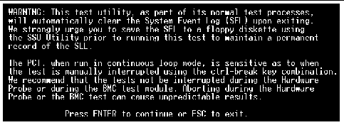
2. Press any key to bring up the warning screen shown in FIGURE 4-21.
Note that is it advisable to save the System Event Log to a floppy before running the PCT and that it is recommended that testing not be interrupted during the hardware probe or during the BMC test.
 [ D ]
[ D ]
3. Press Enter to continue or Esc to exit.
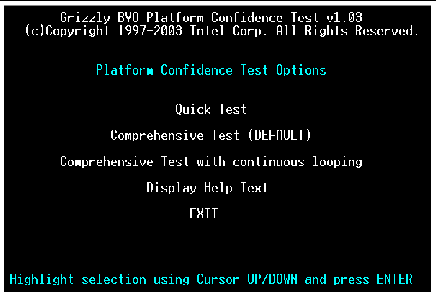
If you press Enter, the screen shown in FIGURE 4-22 appears.
 [ D ]
[ D ]
You can use this menu to perform the following tests:
All test results are saved in the RESULT.LOG file of the current directory, which is normally C:\PCT. This file is overwritten for each test.
This test performs a quick test of the CPU(s), DIMM memory, CPU cache memory, and hard disk drives. It is not a complete test of these units.
Quick Test takes from 2 to 5 minutes, depending on the amount of DIMM memory installed. The following test modules are run during Quick Test:
To run the Quick Test, follow this procedure:
1. Select Quick Test using the arrow keys and press Enter.
The initial testing produces a screen similar to the one shown in FIGURE 4-23. This phase of the testing determines your server configuration.
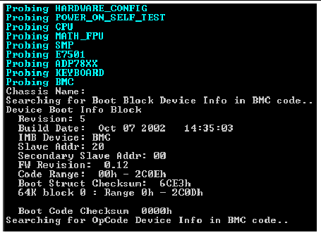
More screen entries appear as the test progresses. Eventually the screen shown in FIGURE 4-24 appears.
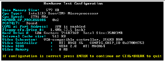
This screen indicates the hardware configuration that has been determined from the initial tests.
2. If the hardware configuration does not match the configuration of your server, press the Ctrl and Break keys simultaneously (Ctrl + Break).
You are prompted to check all the cables and your server configuration, then you are exited to the Platform Confidence Test main menu.
3. If the configuration is correct, press Enter to continue.
Several entries are displayed and scroll past on the screen, showing the test progress (see FIGURE 4-25).
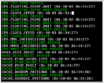
When the testing is done, the results are summarized (see FIGURE 4-26).
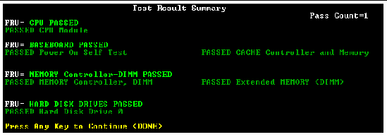
4. Press any key to see the analog sensor readings (see FIGURE 4-27).
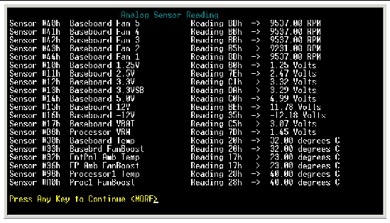
5. Press any key to see the remaining sensor readings (see FIGURE 4-28).
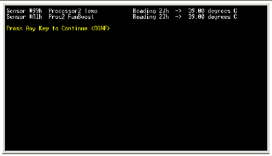
6. Press any key to return to the main Platform Confidence Test menu.
To view the test results, follow this procedure:
7. Return to the System Utilities submenu (see FIGURE 4-16) and use the Quit to DOS menu selection to exit to DOS.
C:\PCT
9. Type the following command:
Type RESULT.LOG | more
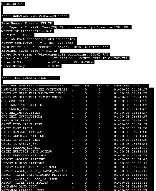
A portion of the RESULT.LOG file is displayed each time you press a key. In this way, you can see the results, which are divided into the following sections:
The RESULT.LOG file is overwritten each time you run a test. A sample of the RESULT.LOG file is shown in FIGURE 4-29.
This test fully exercises and tests the server system. The test takes approximately 15 to 20 minutes to execute, depending on the amount of memory installed. The following test modules are run during the Comprehensive Test:
To run the Comprehensive Test, follow this procedure:
1. Select Comprehensive Test using the arrow keys and press Enter.
The initial testing determines your server configuration, and produces screens similar to those shown in FIGURE 4-30 and FIGURE 4-31.
2. When you are prompted about the configuration of the server, if the hardware configuration does not match the configuration of your server, press the Ctrl and Break keys simultaneously (Ctrl+Break).
You are prompted to check all the cables and your server configuration, then you are exited to the Platform Confidence Test main menu.
3. If the configuration is correct, press Enter to continue.
The lines that are displayed and scroll past on the screen show the test progress (see FIGURE 4-30). The information is much more detailed than that displayed for the Quick Test.
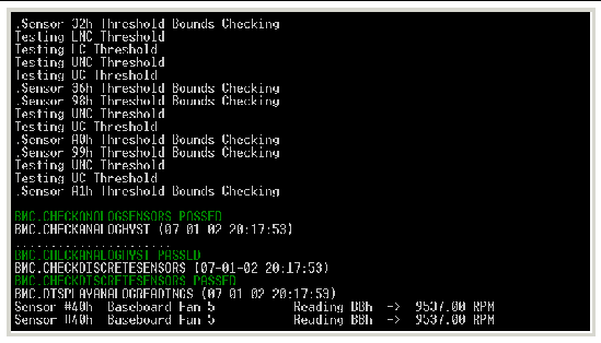
When the testing is done, the results are summarized (see FIGURE 4-31).
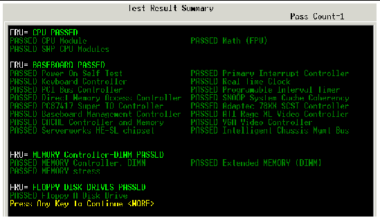
4. Press any key to see the remaining test results.
5. After the remaining test results are displayed, press any key to see the analog sensor readings (similar to the screens shown in FIGURE 4-27 and FIGURE 4-28).
6. After the analog sensor readings are displayed, press any key to return to the main Platform Confidence Test menu.
7. You can view the RESULT.LOG file in a similar fashion to that previously explained.
This test performs the same test as the Comprehensive Test, but runs continuously until stopped. To stop the testing and display the test pass count, press Ctrl + Break. The number of successful test loops executed is shown as "Pass Count = n" at the upper right side of the screen.
The run time for this test is approximately 15 to 20 minutes per pass, depending on the amount of memory installed.
|
Note - The Comprehensive Test should be run after changing any FRU, CRU, or adding an optional component. |
Use this menu selection to update the Baseboard Management Controller (BMC) firmware. The BMC code resides both on the Sun Fire V60x and Sun Fire V65x servers Diagnostics CD and on the Service Partition in the C: /BMC directory. The BMC firmware can also be updated from a standalone, bootable floppy diskette
Use this menu selection to update the hard disk controller firmware. The hot-swap controller (HSC) code resides both on the Sun Fire V60x and Sun Fire V65x servers Diagnostics CD and on the Service Partition in the C: /HSC directory. The HSC firmware can also be updated from a standalone, bootable floppy diskette.
Use this menu item to re-inventory the FRUs and Sensor Data Records (SDR) on the Sun Fire V60x and Sun Fire V65x servers. The FRU/SDR code resides both on the Sun Fire V60x and Sun Fire V65x servers Diagnostics CD and on the Service Partition in the C: /FRUSDR directory.
Typically, the product and chassis serial numbers are changed only by field service personnel when hardware is changed. The asset tag number is intended for use by customers for their internal tracking system. For example, the asset tag might be updated after a firmware or software update.
Use this menu item to update the BIOS Boot block in the event that the boot block becomes corrupted. Use this menu item to also update the BIOS in the event that the BIOS becomes corrupted or if you want to set the BIOS settings back to their defaults. A reboot occurs automatically after the update is complete. The BIOS code resides both on the Sun Fire V60x and Sun Fire V65x servers Diagnostics CD and on the Service Partition in the C: /BIOS directory. The BIOS can also be updated from a standalone, bootable floppy diskette See Updating the Server Configuration for information on how to update the BIOS.
Selecting this menu item causes a reboot to the service partition.
Choosing this menu item causes a reboot, maintaining normal boot device ordering.
The Sun Fire V60x and Sun Fire V65x servers Diagnostics CD provides basic server configuration software through a text-based menu program that runs when the server boots from the CD. After bootup, the CD runs a menu program that allows the user to create driver diskettes, run utilities, update system components, and install and manage service partitions. The CD ships with all Sun Fire V60x and Sun Fire V65x servers and can used by Sun service personnel as well as end customers.
To begin using the diagnostics CD, follow these steps:
1. Reboot the Sun Fire V60x and Sun Fire V65x servers with the diagnostics CD inserted in the CD tray.
|
Note - You will need to make sure that the boot sequence is such that the diagnostics CD is selected as a boot device before the hard disk. This is normally the case by default. Refer to BIOS Setup Utility <F2> for more information on how to change the boot sequence. |
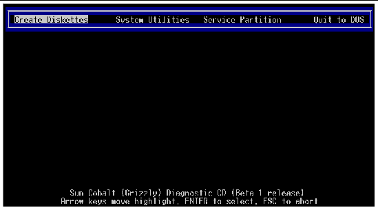
After bootup, verify that a DOS-like menu appears similar to that of the Service Partition menu (see Service Partition Menu), except that there is one more item at the top of the screen for managing the service partition, as shown in FIGURE 4-32. This menu works in both local and remote (console redirection) modes, and allows you to create driver and utilities diskettes, run system utilities, and create, format, or remove a service partition.
With the diagnostics CD menu, you can perform the operations listed in following sections.
For more information on creating diskettes, see Create Diskettes.
For more information on running system utilities, see System Utilities.
This menu item (see FIGURE 4-32) allows you to find, create, format, or remove a service partition on the hard disk of the Sun Fire V60x and Sun Fire V65x servers.

|
Caution - If you remove the service partition, it possible that you may have to reformat the hard disk to create it again. Reformatting the disk removes all partitions and destroys all data on the disk.
|
You can create service partitions on any disk you specify, as long as a service partition or any other partition does not already exist. There is only one service partition allowed. Some operating systems automatically create the service partition when they install.
If you want to reformat the service partition and copy the CD contents to the service partition, select Service Partition > Run Service Partition Administrator and use option 4 (Format service partition and install software) from the resulting menu (see FIGURE 4-34). This updates the service partition only.
If the Sun Fire V60x and Sun Fire V65x servers do not have a service partition installed for some reason (for example, if you running Red Hat Linux), the Service Partition Administrator tool on the CD will not be able to create a service partition. However, from Linux you can create a type 12 (Compaq Diagnostics) partition, which is the only partition type the CD tool understands.
If you are performing a generic Red Hat install, you should create the service partition first and then install Red Hat Linux using the option to preserve existing partitions. As shipped from the factory, the Sun Fire V60x and Sun Fire V65x servers service partition already exists (sda1 for single drive systems and sdb1 for dual drive systems). Just make sure during Red Hat Linux installation to leave these partitions alone.
If you have a server with preinstalled Solaris 9 software, you do not have to create a service partition. If you are performing a custom Solaris installation and the service partition does not exist on the server, you will need to install the service partition before performing the Solaris installation.
If the hard disk service partition is removed, erased, or damaged, you can use the diagnostics CD to restore it, depending on the extent of the problem.
If the contents of the service partition have been removed, erased, or damaged but the sda1 or sdb1 partitions still exist:
1. Boot from the diagnostics CD.
After the server has booted, the screen shown in FIGURE 4-33 appears.
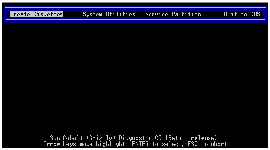
2. Select Service Partition > Run Service Partition Administrator.
The Service Partition Administration Menu shown in FIGURE 4-34 appears.
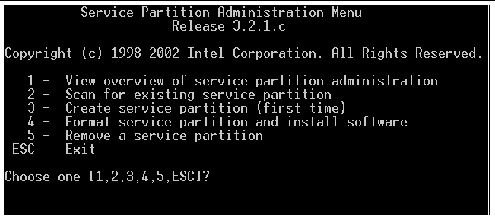
3. Select option 4 to reformat the partition.
The partition will be reformatted and the diagnostic software will be loaded on the partition.
|
Note - The service partition is mounted as /diag when running Linux |
If the service partition was completely removed (intentionally or accidentally) with Linux fdisk:
1. In Linux, go into fdisk and manually create a type 12 partition that is at least 41 MB in size on either sda1 or sdb1 (or the sdc drive for that matter, if it is installed).
2. Reboot the system from the CD.
3. Select Service Partition > Run Service Partition Administrator and then choose option 4.
The partition will be reformatted and the diagnostic software will be loaded on the partition.
For instructions on installing the service partition in a the Sun Fire V60x and Sun Fire V65x servers running the Solaris operating environment, refer to the Sun Fire V60x and Sun Fire V65x Server Solaris Operating Environment Installation Guide (817-2875-xx).
There are several methods for updating the server's configuration. They are explained in the following sections.
1. Insert the BIOS update diskette into the server and reboot.
The prompt shown in FIGURE 4-35 appears

A window appears (see FIGURE 4-36) indicating that the BIOS update is in progress. The floppy disk activity light is illuminated during the update as the BIOS image is copied to the server's flash memory.
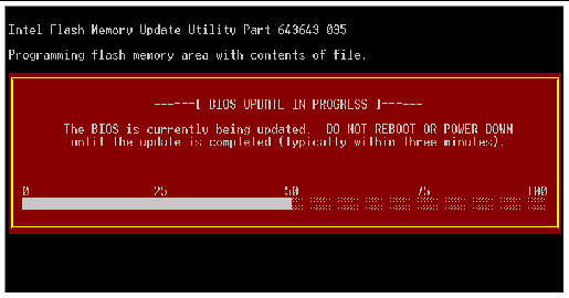

|
Caution - Do not attempt to reboot or power down the server while the BIOS is being updated. You may get unpredictable results. |
When the first update pass is finished, the screen shown in FIGURE 4-37 appears.
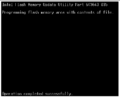
The next screen appears as the BIOS update continues
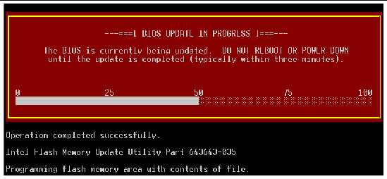
After the update is complete, the CMOS is cleared and the server reboots.
At this point the server boot block and BIOS code have been updated.
3. When the system reboots (the screen clears), power the system off.
4. Remove the floppy diskette.
6. Press "F2" to enter BIOS setup
7. When you reach the BIOS setup screen, press F10 to save and exit.
As bootup continues, the system may report that the Clear CMOS jumper needs to be returned to its original position. If this is displayed, simply power the server off for 30 seconds and power back up.
This completes the Windows BIOS update procedure.
8. To verify the BIOS has been updated, observe the BIOS Build number as the server boots up (see FIGURE 4-39).
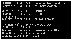
If an update to the system BIOS is not successful or if the system fails to complete POST and BIOS is unable to boot an operating system, it may be necessary to run the BIOS recovery procedure.
|
Note - Recovering the BIOS is the last resort, used only when the main system BIOS will not boot or is corrupt. |
Follow these steps to perform a BIOS recovery:
2. Remove the top cover of the server.
3. Move the RCVR\BOOT jumper located on the baseboard to the Recover position (see FIGURE 4-40).
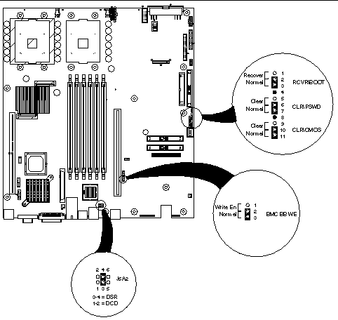
With the jumper in the recovery position, the BIOS is able to execute the recovery BIOS (also known as the boot block) instead of the normal BIOS. The recovery BIOS is a self-contained image that exists solely as a fail-safe mechanism for installing a new BIOS image.
4. Insert a bootable BIOS recovery diskette containing the new BIOS image files.
The recovery BIOS boots from the DOS bootable recovery diskette and the server emits a single beep when it passes control to DOS.
The server also emits a single beep to indicate the beginning of the flash operation.
After a period of time, the BIOS emits two beeps to indicate that the flash procedure was completed successfully.
If the flash procedure fails, the BIOS emits a continuous series of beeps.
When the flash update completes:
2. Remove the floppy diskette.
3. Restore the RCVR\BOOT jumper to its original position.
The system should now boot normally using the updated system BIOS.
You may restart or shut down the Sun Fire V60x and Sun Fire V65x servers using software or hardware.
This section describes the software shutdown commands supported by Linux and Solaris.
The following software mechanisms are available for shutting down a Linux system:
|
Note - The USB port is disabled until an OS and the USB drivers are installed. A PS/2 type keyboard and/or mouse may be required for initial bootup and configuration. |
The following software mechanisms are available for shutting down a Solaris system:
The following hardware mechanisms are available:

|
Caution - These hardware mechanisms are not recommended and should be used only as a last resort. |
Copyright © 2003, Sun Microsystems, Inc. All rights reserved.