| C H A P T E R 2 |
|
Environmental Monitoring |
The Netra CP2300 board uses an intelligent fault detection environmental monitoring system that increases uptime and manageability of the board. The System Management Controller (SMC) module on the Netra CP2300 supports the temperature and voltage environmental monitoring functions. This chapter describes the specific environmental monitoring functions of the Netra CP2300.
|
Note - Environmental monitoring refers to the functionality that was previously called Advanced System Monitoring (ASM) in the Netra CPU board documentation. |
This chapter includes the following sections:
TABLE 2-1 lists the compatible environmental monitoring hardware, OpenBoot PROM, and Solaris operating environment for the Netra CP2300.
|
Solaris 8 2/02 operating environment or subsequent compatible versions |
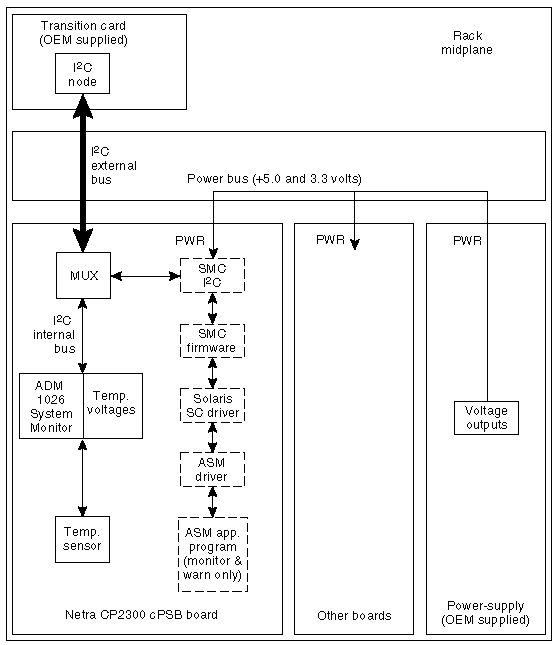
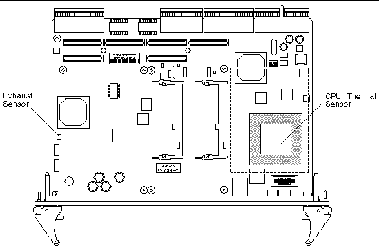
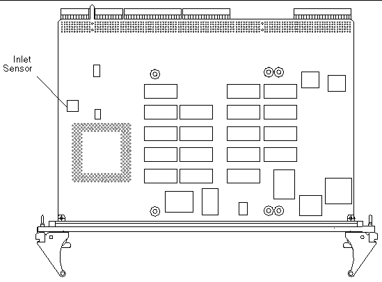
FIGURE 2-1 illustrates the Netra CP2300 environmental monitoring application block diagram. For locations of the temperature sensors, see FIGURE 2-2 and FIGURE 2-3.
|
Note - In FIGURE 2-1, ASM refers to the environmental monitoring functionality. The ASM driver is no longer used on the Netra CP2300 board. |

The Netra CP2300 functions as a node board in a cPSB system rack. The Netra CP2300 monitors its CPU diode temperature and issues warnings at both the OpenBoot PROM and Solaris operating environment levels when these environmental readings are out of limits. At the Solaris operating environment level, the application program monitors and issues warnings for the board. At the OBP level, the CPU diode temperature is monitored if the NVRAM variable
env-monitor is enabled.
This section describes a typical environmental monitoring cycle from power up to shutdown.
The OpenBoot PROM monitors the CPU diode temperature at the fixed polling rate of 10 seconds and displays warning messages on the default output device whenever the measured temperature exceeds the pre-programmed NVRAM module configurable variable warning temperature (the warning-temperature parameter), the critical temperature (the critical-temperature parameter), or the shutdown temperature (the shutdown-temperature parameter). See OpenBoot PROM Environmental Parameters for information on changing these pre-programmed parameters.
OpenBoot PROM-level protection takes place only when the env-monitor parameter is enabled (it is the default setting). If the NVRAM variable env-monitor is set to enabled-with-shutdown
(env-monitor=enabled-with-shutdown), and if the board temperature exceeds the shutdown temperature, the OpenBoot PROM will shut down power to the Netra CP2300 CPU. If the NVRAM variable env-monitor is set to enabled (env-monitor=enabled), the OpenBoot PROM will send a warning, critical, or shutdown temperature message to the user that the Netra CP2300 is overheating.
Disabling env-monitor completely disables environmental monitoring protection at the OpenBoot PROM level but does not affect environmental monitoring protection at the Solaris operating environment level.
|
Note - To protect the system at OpenBoot PROM level, the env-monitor should be enabled at all times. |
Monitoring changes in the sensor temperatures can be a useful tool for determining problems with the room where the system is installed, functional problems with the system, or problems on the board. Establishing baseline temperatures early in deployment and operation could be used to trigger alarms if the temperatures from the sensors increase or decrease dramatically. If all the sensors go to room ambient, power has probably been lost to the host system. If one or more sensors rise in temperature substantially, there may be a system fan malfunction, the system cooling may have been compromised, or room air conditioning may have failed.
Protection at the operating environment level takes place when the PICL environmental monitoring program (envmond) is running. The environmental monitoring program is part of a Unix daemon that runs automatically when Solaris boots up.
In a typical environmental monitoring application program, the software reads the CPU, inlet, and exhaust temperature sensors once every polling cycle. The program then compares the measured CPU diode temperature with the warning temperature and displays a warning message on the default output device whenever the warning temperature is exceeded.
The program can also issue a shutdown message on the default output device whenever the measured CPU diode temperature exceeds the shutdown temperature. In addition, the envmond application program can be programmed to sync and shut down the Solaris operating environment when conditions warrant.
Refer to Sample Application Program for an example of how a simple envmond program can be implemented.
The power module is controlled by the SMC subsystem (except for automatic controls such as overcurrent shutdown or voltage regulation). The functions controlled are core voltage output level and power sequencing/monitor.
The onboard voltage controller is a hardware function that is not controlled by either firmware or software. At the OpenBoot PROM level, if the NVRAM variable env-monitor is set to enabled-with-shutdown (env-monitor=enabled-with-shutdown), and if the board temperature exceeds the shutdown temperature, the OpenBoot PROM will shut down power to the Netra CP2300 CPU.
There is no mechanism for the Solaris operating environment to either recover or restore power to the Netra CP2300 when an unusual condition occurs (for example, if the CPU diode temperature exceeds its maximum recommended level). In either case, the end user must intervene and manually recover the Netra CP2300 as well as the cPSB system through hardware control. Once a shutdown has occurred, you can recover the board using a cold-reset IPMI command to SMC or by extracting and reinserting the board.
This section summarizes the hardware environmental monitoring features on the Netra CP2300 board. TABLE 2-2 lists the environmental monitoring functions on a Netra CP2300 board.
TABLE 2-3 shows the I2C components.
FIGURE 2-2 and FIGURE 2-3 show the location of the environmental monitoring hardware on the Netra CP2300.


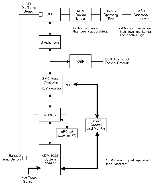
FIGURE 2-4 is a block diagram of the environmental monitoring functions.
|
Note - In FIGURE 2-4, ASM refers to the environmental monitoring functionality. The ASM driver is no longer used on the Netra CP2300 board. The ASM device driver block in Figure 3-4 should be replaced with SC device driver. |
 [ D ]
[ D ]
The onboard voltage controller allows power to the CPU of the Netra CP2300 only when the following conditions are met:
The controller requires these conditions to be true for at least 100 milliseconds to help ensure the supply voltages are stable. If any of these conditions become untrue, the voltage monitoring circuit shuts down the CPU power of the board.
The CPU diode sensor reading may vary from slot to slot and from board to board in a system, and is dependent primarily on system cooling. As an example, a system may have sensor readings for the CPU diode from 35°C to 49°C with an ambient inlet of 21°C across many boards, with a variety of configurations and positions within a chassis. Care must be taken when setting the alarm and shutdown temperatures based on the CPU diode sensor value. This sensor typically is linear across the operating range of the board.
The exhaust sensor measures the local air temperature at the trailing edge of the board for systems with bottom to top airflow. This value depends on the character and volume of the airflow across the board. Typical values in a chassis may range from a delta over inlet ambient of 0°C to 12°C, depending on the power dissipation of the board configuration and the position in the chassis. The exhaust sensor is nonlinear with respect to ambient inlet temperature.
The inlet sensor measures the local air temperature at the leading edge of the board on the solder-side under the solder-side cover. This value typically can range from a reading of 0°C to 13°C above inlet system ambient in a chassis; care must be taken to understand the application and installation of the board to use this temperature sensor.
A sudden drop of all temperature sensors close to or near room ambient temperature can mean loss of power to one or more Netra CP2300s.
A gradual increase in the delta temperature from inlet to outlet can be due to dust clogging system filters. This feature can be used to set service levels for filter cleaning or changing.
The CPU diode temperature can be used to prevent damage to the board by shutting the board down if this sensor exceeds predetermined limits.
The Netra CP2300 uses the environmental monitoring detection system to monitor the temperature of the board. The environmental monitoring system will display messages if the board temperature exceeds the set warning, critical, and shutdown settings. Because the on-board sensors may report different temperature readings for different system configurations and airflows, you may want to adjust the warning, critical, and shutdown temperature parameter settings.
The Netra CP2300 determines the board temperature by retrieving temperature data from sensors located on the board. A board sensor reads the temperature of the immediate area around the sensor. Although the software may appear to report the temperature of a specific hardware component, the software is actually reporting the temperature of the area near the sensor. For example, the CPU diode sensor reads the temperature at the location of the sensor and not on the actual CPU heat sink. The board's OpenBoot PROM collects the temperature readings from each board sensor at regular intervals. You can display these temperature readings using the show-sensors OpenBoot PROM command. See show-sensors Command at OpenBoot PROM.
The temperature read by the CPU sensor will trigger OpenBoot PROM warning, critical, and shutdown messages. When the CPU sensor reads a temperature greater than the warning parameter setting, the OpenBoot PROM will display a warning message. Likewise, when the sensor reads a temperature greater than the shutdown setting, the OpenBoot PROM will display a shutdown message.
Many factors affect the temperature readings of the sensors, including the airflow through the system, the ambient temperature of the room, and the system configuration. These factors may contribute to the sensors reporting different temperature readings than expected.
TABLE 2-4 shows the sensor readings of a Netra CP2300 operating in a Sun server in a room with an ambient temperature of 21°C. The temperature readings were reported using the show-sensors OpenBoot PROM command. Note that the reported temperatures are higher than the ambient room temperature.
|
Difference Between Reported and Ambient Room Temperature (in Degrees Celsius) |
||
|---|---|---|
Since the temperature reported by the CPU diode sensor might be different than the actual CPU temperature, you may want to adjust the settings for the warning-temperature, critical-temperature, and shutdown-temperature OpenBoot PROM parameters. The default values of these parameters have been conservatively set at 74°C for the warning temperature, 79°C for the critical temperature, and 91°C for the shutdown temperature.
|
Note - If you have developed an application that uses the environmental monitoring software to monitor the temperature sensors, you may want to adjust your application's settings accordingly. |
This section describes how to change the OpenBoot PROM environmental monitoring parameters. These global OpenBoot PROM parameters do not apply at the Solaris level. Instead, the environmental monitoring application program provides equivalent parameters that do not necessarily have to be set to the same values as their OpenBoot PROM counterparts. Refer to Environmental Monitoring Application Programming for information about using environmental monitoring at the Solaris level. The OpenBoot PROM polling rate is at fixed intervals of 10 seconds.
OBP programs SMC for temperature monitoring using the sensor commands. On a Netra CP2300, there are three NVRAM variables that provide different temperature levels. The critical-temperature limit lies between warning and shutdown thresholds. The default values of these temperature thresholds and corresponding action are shown in TABLE 2-5.
|
OBP shuts down the CPU processor and the Netra CP2300 board if
|
Note that there is a lower limit of 50° C on shutdown-temperature value. If you try to set the temperature to a value lower than 50° C, OpenBoot PROM will not accept it. This safeguards a user from setting the shutdown-temperature lower than the room temperature and thereby causing the CPU processor and the Netra CP2300 to be powered off by SMC on the next reset.
The warning-temperature global OpenBoot PROM parameter determines the temperature at which a warning is displayed. The shutdown-temperature global OpenBoot PROM parameter determines the temperature at which the system is shut down. The temperature monitoring environment variables can be modified at the OpenBoot PROM command level as shown in examples below:
The critical-temperature is a second-level warning temperature with a default value of 79° C. This variable can be modified using the OpenBoot PROM level setenv command as shown in example below:
This section describes the OpenBoot PROM environmental monitoring functions.
The following NVRAM module environmental monitoring variables are in OpenBoot PROM.
When the CPU diode temperature reaches "warning-temperature," a similar message is displayed at the ok prompt at a regular interval:
Temperature sensor #2 has threshold event of <<< WARNING!!! Upper Non-critical - going high >>> The current threshold setting is : 74 The current temperature is : 75 |
When the CPU diode temperature reaches "critical-temperature," a similar message is displayed at the ok prompt at a regular interval:
Temperature sensor #2 has threshold event of <<< !!! ALERT!!! Upper Critical - going high >>> The current threshold setting is : 79 The current temperature is : 80 |
The show-sensors command at OpenBoot PROM displays the readings of all the temperature sensors on the board. A sample output for typical sensor readings for a Netra CP2300 is as follows:
The Intelligent Platform Management Interface (IPMI) commands can be used to enable the sensors monitoring and subsequent event generation from other boards in the system.
The IPMI command examples provided in this section are based on the IPMI Specification Version 1.0. Please use the IPMI Specification for additional information on how to implement these IPMI commands.
|
Note - To execute an IPMI command, at the OpenBoot PROM ok prompt, type the packets in reverse order followed by the relevant information as shown in examples in Examples of IPMI Command Packets. Change the bytes in the example packet to accommodate different IPMI addresses, different threshold values or different sensor numbers. See also the IPMI Specification Version 1.0. |
The command execute-smc-cmd is available in SMC controller device mode
(/pci@1f,0/pci@1,1/isa@7/sysmgmt@0,8010 alias hsc). You need to go to the sysmgmt node before executing the command execute-smc-cmd using the following:
1. Set the thresholds for the sensors.
See Set Sensor Threshold. If no threshold is set, the default threshold operates:
2. Follow instructions in Check Whether the IPMI Commands Are Executed Properly to check proper execution of the command.
1. To execute a command to enable events from the sensor, type:
See Set Sensor Event Enable Command and Get Sensor Event Enable.
There are supporting commands for any sensor and the corresponding packets at these commands: get sensor threshold, get sensor reading, and get sensor event enable.
2. Follow instructions in Check Whether the IPMI Commands Are Executed Properly to check proper execution of the command.
1. Check whether the stack on the ok prompt displays 0 when the command is issued.
A 0 indicates that the command packet sent to the board was successful.
2. Type execute-smc-cmd (cmd 33) command at the ok prompt as follows:
This command verifies that the target satellite board received and executed the command and sent a response.
3. Check the completion code which is the seventh byte from left.
If the completion code is 0, then the target board successfully executed the command. Otherwise the command was not successfully executed by the board.
4. Check that rsSA and rqSA are swapped in the response packet.
The rsSA is the responder slave address and the rqSA is the requestor slave address.
5. (Optional) If command not correctly executed, resend the IPMI command.
The following packets are IPMI command packets that can be sent from the OpenBoot PROM ok prompt:
A typical example of the sensor command is as follows:
A typical example of the sensor command is as follows
A typical example of the sensor command is as follows:
A typical example of the sensor command is as follows:
A typical example of the sensor command is as follows:
|
Note - The NetFN/LUN for all sensor IPMI commands is 12, which implies that the netFn is 0x04 lun= 0x2. |
The following sections describe how to use the environmental monitoring functions in an application program.
For the environmental monitoring application program (envmond) to monitor the hardware environment, the following conditions must be met:
The environmental monitoring parameter values in the application program apply when the system is running at the Solaris level and do not necessarily have to be the same as the corresponding to the parameter settings in the OpenBoot PROM.
To change the environmental monitoring parameter setting at the OpenBoot PROM level, see OpenBoot PROM Environmental Parameters for the procedure. The OpenBoot PROM environmental monitoring parameter values only apply when the system is running at the OpenBoot PROM level.
Temperature sensor states may be read using the libpicl API. The following properties are supported in a PICL temperature sensor class node:
The PICL plug-in receives these sensor events and updates the State property based on the information extracted from the IPMI message. It then posts a PICL event.
Threshold levels of the PICL node class temperature sensor are:
To obtain a reading of temperature sensor states, use the prtpicl -v command:
PICL output of temperature sensors on a Netra CT system is shown in CODE EXAMPLE 2-1.
The PICL envmond plug-in opens a SMC driver stream and requests sensor events. The SMC monitors the sensors and generates an event when it detects a change at a particular sensor which meets one of the specified thresholds and generates an event to local Solaris software. This event is captured by the SMC driver (as an IPMI message) and is sent on an open STREAM that has requested sensor events. The sensor events are received by the PICL plug-in. The PICL plug-in updates the State property based on the information it extracts from the IPMI message and posts a PICL event.
This section presents a sample environmental monitoring (envmond) application that monitors the CPU diode temperature.
You can access the CPU temperature sensor current readings and environmental monitoring settings from the Solaris prompt by typing the following commands. Sample output is listed after each command.
TABLE 2-7 shows which Solaris commands correspond to the environmental monitoring warning that runs when the CPU temperature exceeds the set limit.
|
The CPU shutdown message is displayed and the CPU is shut off. |
Copyright © 2004, Sun Microsystems, Inc. All rights reserved.