C H A P T E R  3

Configuring the Clustered Database Platform

This chapter covers the configuration and setup of the hardware and preinstalled software on the Clustered Database Platform 280/3 system, which includes the following topics:


Before You Begin

Before performing the steps in this chapter, you must have already completed the following:

Refer to the clustered platform documentation that came with the system for instructions on how to perform these tasks.


Note - The software installation and configuration instructions in this guide supersede equivalent instructions in the other manuals you might have received. For the latest and most current information on this clustered platform, refer to the Clustered Database Platform 280/3 With Oracle9i Database Real Application Clusters, Late-Breaking News document. See Clustered Database Platform Documentation for instructions on locating this document.


Collecting Site-Specific Information

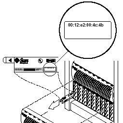
Use FIGURE 3-1 to record site-specific information that is needed to complete the procedures in this guide. Names and addresses shown in the center column represent the examples used in this guide. Assign names and addresses (routed or non-routed) that are appropriate for your site.

TABLE 3-1 Site-Specific Information Worksheet

Item

Example
Used In this Guide

Your Value

Terminal concentrator

Name

TC


IP address (admin network)

192.168.0.2


Subnet mask1

255.255.255.0


Load host address1

0.0.0.0


Broadcast address

192.168.0.255


Dump address1

0.0.0.0


Management Server


Host name

sc3sconf1-ms


IP address (eri0 on admin net)

192.168.0.1


Subnet mask1

255.255.255.0


Default router IP address (admin net)


198.168.0.248


Cluster

Environment

Name

sc


Default router IP address

router_IP_address


Network mask1

255.255.255.0


Cluster Node 1


Name

node1


IP address
(qfe0 on production network)


node1_IP_address


Ethernet address

8:0:20:fb:29:8e


Cluster Node 2


Name

node2


IP address
(qfe0 on production network)


node2_IP_address


Ethernet address

8:0:20:fb:1a:55


Internal Admin Network Addresses

Internal network IP address

10.0.0.0


Network mask1

255.255.255.0


Management server IP address (eri1)


10.0.0.1


network hostname

MS-280R-admin

Set automatically

Cluster node 1, IP address

10.0.0.2


Cluster node 1, hostname

node1-admin

Set automatically

Cluster node 2, IP address

10.0.0.3


Cluster node 2, hostname

node2-admin

Set automatically

T3 Array 1

Name

T3-01


Internal network IP address

10.0.0.4


Ethernet address2

(two digits between each colon)


00:20:f2:00:3e:a6


T3 Array 2

Name

T3-02


Internal network IP address

10.0.0.5


Ethernet address2

(must have two digits between each colon)


00:20:f2:00:04:d6


Other


Private interconnect
IP address1


172.16.0.0


Private interconnect Netmask1

255.255.0.0


Choose one volume manager product:

  • Solstice DiskSuite
  • VERITAS Volume Manager3


(Optional) Two VERITAS
license keys: node 1

node 2


1. The default value is often an acceptable choice for this address.2. The Ethernet address for each cluster node is located on the Customer Information, System Record sheet supplied with your system. Use the serial number on the information sheet and on the back of each node to correctly identify the Ethernet address. Ethernet addresses are located on the T3 arrays as shown in FIGURE 3-1.3. You must obtain two VERITAS license keys if you intend to use the VERITAS Volume Manager product on your Cluster Platform. These license keys are not needed if you plan to use Solstice DiskSuite instead of VERITAS Volume Manager.

FIGURE 3-1 shows the location of the Ethernet address for the arrays.

 FIGURE 3-1 Location of Ethernet Address on Sun StorEdge Disk Array Pull Tab

Line art showing the Ethernet address pull-tab on the Sun StorEdge Disk array.


Configuring the Software

When your system is shipped from the factory, the management server is pre-loaded with all of the necessary software to install the Solaris operating environment and Sun Cluster software on the cluster nodes. You must configure the terminal concentrator first.


caution icon

Caution - You must enter the correct parameters during the initial configuration, or the system will not configure properly.


procedure icon  To Configure the Terminal Concentrator

Because the Cluster Platform does not have a monitor, it is only accessible from another system that you provide (referred to as the local system in this guide). The local system is simply used as a remote display to the management server, and it must be connected to the same network as the Cluster Platform. You do not need to permanently dedicate any particular system as the local system. It can be any system that is convenient at the time. For the first several steps, however, the local system needs to be in close proximity to the Cluster Platform (for connecting a temporary cable connection for tip) and it should be running Solaris (or use a laptop as described in Appendix B).

1. Power on the expansion cabinet power sequencers, and then power on all individual system components, except for the Sun StorEdge T3 disk arrays.


caution icon

Caution - Do not power on the Sun StorEdge T3 disk arrays until instructed to do so on "Invalid Cross-Reference Format".


2. Provide console connectivity from the local system to the terminal concentrator:


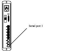
Note - The initial access to the terminal concentrator is performed using the tip command through a serial port of the local system to Port 1 of the terminal concentrator.


a. Disconnect the serial cable (part no. 530-9524) from Port 1 of the terminal concentrator.

b. Connect the RJ-45 end of the serial cable (part no. 530-2151) to Port 1 of the terminal concentrator and the other end, DB-25 male, to serial port B of your
local system.

 FIGURE 3-2 Terminal Concentrator Serial Port 1

Line art showing serial port 1 on the terminal concentrator.

3. From a terminal window on the local system, type the following command:

# /usr/bin/tip hardwire

The tip(1M) command connects the local system I/O to the terminal concentrator I/O during an interactive session.


Note - If the port is busy, see Appendix C for information on configuring another port for a tip connection.


4. Configure the terminal concentrator:

  • Power on the terminal concentrator.
  • Within 5 seconds after power on, press and release the TEST button.

The terminal concentrator undergoes a series of diagnostics tests that take approximately 60 seconds to complete.

Following the diagnostics tests, the tip window of the local system displays:

System Reset - Entering Monitor Mode 
monitor::

5. Configure the network addressing information for the terminal concentrator.

Use the addr, addr -d, and sequence commands to modify and verify the network configuration of the terminal concentrator. Refer to your completed worksheet for the network address information.

In the following example, replace the addresses shown in italics with the appropriate addresses for your network environment.

monitor:: addr
 Enter Internet address [0.0.0.0]:: 192.168.0.2
 Internet address: 192.168.0.2
 Enter Subnet mask [255.255.0.0]:: 255.255.255.0
 Subnet mask: 255.255.255.0 
 Enter Preferred load host Internet address [<any host>]::0.0.0.0
 Preferred load host address: 0.0.0.0
 Enter Broadcast address [0.0.0.0]:: 192.168.0.255
 Broadcast address: 192.168.0.255
 Enter Preferred dump address [0.0.0.0]::0.0.0.0
 Preferred dump address: 0.0.0.0
 Select type of IP packet encapsulation (ieee802/ethernet) [<ethernet>]:: ethernet
 Type of IP packet encapsulation: <ethernet> :: ethernet 
 Load Broadcast Y/N [Y]:: N
 Load Broadcast: N
 
monitor:: addr -d
 Ethernet address (hex): 00-80-2D-ED-21-23
 Internet address: 192.168.0.2
 Subnet masks: 255.255.255.0
 Preferred load host address: 0.0.0.0
 Broadcast address: 192.168.0.255
 Preferred dump address: 0.0.0.0
 Type of IP packet encapsulation: ethernet
 Load Broadcast: N
 
monitor:: sequence
 
Enter a list of 1 to 4 interfaces to attempt to use for downloading code or upline dumping. Enter them in the order they should be tried, separated by commas or spaces. Possible interfaces are:
 
 Ethernet: net
 SELF: self
 
Enter interface sequence [net]:: self
 Interface sequence: self

6. Terminate your tip session by entering ~. (tilde and period).

monitor:: ~.

7. Power cycle the terminal concentrator to apply the IP address changes and wait at least two minutes for the terminal concentrator to activate its network.

8. Return the system to the factory cable configuration:

a. Remove the cable that you connected for the earlier tip step.

Disconnect the serial cable (part no. 530-2151) from port 1 of the terminal concentrator and from the local system.

b. Reconnect the serial cable (part no. 530-9524) to Port 1 of the terminal concentrator.


Note - At this time, the cluster configuration should be cabled as originally shipped from the factory.


9. From the local system, type the following command to verify that the terminal concentrator responds to the new IP address:

# /usr/sbin/ping 192.168.0.2
192.168.0.2 is alive

The local system must be connected to the same network to which the terminal concentrator was configured.

10. Access the terminal concentrator using the telnet command:

# telnet 192.168.0.2
Trying 192.168.0.2... 
Connected to 192.168.0.2. 
Escape character is '^]'. 
cli
 
Enter Annex port name or number: cli
Annex Command Line Interpreter   *   Copyright 1991 Xylogics, Inc. 
annex: su
Password: 192.168.0.2 (password defaults to the assigned IP address)


Note - The default password matches the IP address of the terminal concentrator. You can change the default password of the terminal concentrator to avoid unnecessary security exposure. Refer to the terminal concentrator documentation for more information.


11. Edit the terminal concentrator config.annex file:

annex# edit config.annex   

The terminal concentrator opens an editing session for the config.annex file.

12. Type the following information into the config.annex file. Replace 198.168.0.248 with the appropriate default router address for the management server in your network.

% gateway
net default gateway 198.168.0.248 metric 1 hardwired 
 
Ctrl-W: save and exit Ctrl-X: exit Ctrl-F: page down Ctrl-B: page up 

13. Press Ctrl+W to save the changes and exit the config.annex file.

14. Enable access to all ports.

annex# admin
Annex administration MICRO-XL-UX R7.0.1, 8 ports
admin: port all
admin: set port mode slave
       You may need to reset the appropriate port, Annex subsystem 
       or reboot the Annex for changes to take effect.
admin: quit

15. Reboot the terminal concentrator.

annex#: boot
bootfile: <CR>
warning: <CR>
       *** Annex (192.168.0.2) shutdown message from port v1 ***
       Annex (192.168.0.2) going down IMMEDIATELY

After 90 seconds, the terminal concentrator and all ports will be accessible from outside the subnet. Use the /usr/sbin/ping 192.168.0.2 command to determine when the terminal concentrator is ready to be used.


procedure icon  To Configure the Management Server

This section contains the procedure for configuring the management server. You must perform the steps exactly as they appear.

When executing commands on the management server from the local system, verify that the DISPLAY shell environment variable (on the management server) is set to the IP address of the local system (local host).


caution icon

Caution - On the local system, you must set and export the TERM environment variable to a value that emulates the kind of terminal you are using. This setting should also correlate with the terminal emulation you choose on "Invalid Cross-Reference Format" in Step 7. If this is not done, the text might not display properly on the screen, nor match what is in the examples in this guide.


If the TERM value is not set properly, the screen text might display garbled and prevent you from interacting with the installation script after you boot the management server. If this occurs, you must stop the installation and start over.

To stop the installation and start over, perform the following steps:

1. In the telnet window of your local system, press Ctrl+], then type send brk to take the management server to the OpenBoot PROM prompt.

2. At the OpenBoot PROM prompt, boot the management server to single-user mode.

3. Execute the sys-unconfig(1M) command to remove previously defined system parameters.

4. Press Y to confirm the sys-unconfig(1M) questions.

5. Restart the installation of the management server by using the following command:

ok boot disk -s # sys-unconfig


caution icon

Caution - Do not interrupt the installation process during the installation. There are several times that one or more of the cluster components will boot or download software. These activities take time (approximately 15 minutes for the management server to reboot, for example) and must not be interrupted. Do not interrupt the installation process at any time (this includes issuing a Ctrl-C key sequence), or the cluster platform will be left in an unpredictable state.


In the following steps, replace the italicized examples with the appropriate names and addresses from the worksheet.

1. From your local system, access the terminal concentrator:

Telnet to the terminal concentrator, and select Port 1. The following steps will assist you in the configuration of the management server; at the conclusion of the steps, the management server will reboot, and you will be asked a series of questions to configure the cluster.

The following are the port designations:

  • Port 1 = management server
  • Port 2 = cluster node 1
  • Port 3 = cluster node 2
  • # telnet 192.168.0.2
    
    Trying 192.168.0.2... 
    
    Connected to 192.168.0.2. 
    
    Escape character is '^]' <CR>


    Rotaries Defined:
    
        cli


    Enter Annex port name or number: 1
    

2. Press Ctrl+] and type send brk at the telnet prompt to make sure that the management server is at the "ok" OpenBoot PROM prompt.

3. Set auto-boot? to true from the OpenBoot PROM prompt as follows:

ok setenv auto-boot? true

4. Boot the management server from the OpenBoot PROM prompt to start the configuration process.

The management server boots and begins asking you to define information that is specific to your site.

ok boot disk
Resetting... 
LOM event: +17h48m45s host reset
 
@
Netra T1 200 (UltraSPARC-IIe 500MHz), No Keyboard
OpenBoot 4.0, 1 GB memory installed, Serial #16641800.
Ethernet address 8:0:20:fd:ef:8, Host ID: 80fdef08.
 
 
Executing last command: boot disk                                     
Boot device: /pci@1f,0/pci@1/scsi@8/disk@0,0 File and args: 
SunOS Release 5.8 Version Generic_108528-12 64-bit
Copyright 1983-2001 Sun Microsystems, Inc. All rights reserved.
Hostname: unknown
metainit: unknown: there are no existing databases
 
Configuring /dev and /devices
Configuring the /dev directory (compatibility devices)
The system is coming up. Please wait.


caution icon

Caution - The following steps provide critical information for configuring the cluster platform. Use the information you collected in the worksheet.


5. Select a language.

6. Choose a locale.


Note - When the correct terminal type is used, the text at the bottom of most of the screens in steps 3 through 19 shows function keys instead of escape sequences for the options. If the terminal cannot interpret the function keys properly, the screens will show escape sequences. Most of the screens also have different options than those shown in the examples.


Selection screens have two options, escape sequences or:

F2_Continue    F6_Help

Confirmation screens have three options, escape sequences or:

F2_Continue    F4_Change    F6_Help

The only exception to these rules is the Time Zone selection screen, which has a Cancel option:

F2_Continue    F5_Cancel    F6_Help 

7. Select the appropriate terminal emulation:

Choose one of the terminal types from the list that best emulates the kind of terminal you are using on the local system.


caution icon

Caution - Some of the following terminal types cause unpredictable results. The procedures in this book contain code examples based on the DEC VT100 terminal type.


What type of terminal are you using?
 1) ANSI Standard CRT
 2) DEC VT52
 3) DEC VT100
 4) Heathkit 19
 5) Lear Siegler ADM31
 6) PC Console
 7) Sun Command Tool
 8) Sun Workstation
 9) Televideo 910
 10) Televideo 925
 11) Wyse Model 50
 12) X Terminal Emulator (xterms)
 13) Other
Type the number of your choice and press Return: 3

The terminal selection may affect the output displayed during the configuration process. It also may not match the examples in this document. After you select the terminal emulation, network connectivity is acknowledged.

8. Select Yes to the network connectivity question.

The eri0 interface on the management server is intended for connectivity to the administration network.

- Network Connectivity ------------------------------------------
Specify Yes if the system is connected to the network by one of the Solaris or vendor network/communication Ethernet cards that are supported on the Solaris CD. See your hardware documentation for the current list of supported cards.
Specify No if the system is connected to a network/communication card that is not supported on the Solaris CD, and follow the instructions listed under Help.
 
      Networked
      ---------
      [X] Yes
      [ ] No
--------------------------------------------------------------
Esc-2_Continue   Esc-6_Help

9. Deselect Dynamic Host Configuration Protocol (DHCP) services.

Because the management server must have a fixed IP address and name recognized by outside clients, DHCP is not supported for this function:.

- DHCP ----------------------------------------------------------
On this screen you must specify whether or not this system should use DHCP for network interface configuration. Choose Yes if DHCP is to be used, or No if the interfaces are to be configured manually.
 
WARNING: Because this machine booted from the network, DHCP support will not be enabled, if selected, until after the system reboots.
 
      Use DHCP
      --------
      [ ] Yes
      [X] No
--------------------------------------------------------------
Esc-2_Continue   Esc-6_Help

10. Select the primary network interface.

The management server configuration uses eri0 as the default primary network interface. This is the only interface you should configure at this time.

On this screen you must specify which of the following network
adapters is the system's primary network interface. Usually the correct choice is the lowest number. However, do not guess; ask your system administrator if you're not sure.
 
To make a selection, use the arrow keys to highlight the option and
press Return to mark it [X].
 
      Primary network interface
      -------------------------
      [X] eri0
      [ ] eri1
--------------------------------------------------------------
Esc-2_Continue   Esc-6_Help

11. Define the host name of the management server.

- Host Name -----------------------------------------------------
On this screen you must enter your host name, which identifies this system on the network. The name must be unique within your domain; creating a duplicate host name will cause problems on the network after you install Solaris.
 
A host name must be at least two characters; it can contain letters, digits, and minus signs (-).
 
    Host name: sc3sconf1-ms                         
 
--------------------------------------------------------------
Esc-2_Continue   Esc-6_Help

12. Type the IP address for the eri0 port of the management server.

- IP Address ----------------------------------------------------
 
On this screen you must enter the Internet Protocol (IP) address for this system. It must be unique and follow your site's address conventions, or a system/network failure could result.
 
IP addresses contain four sets of numbers separated by periods (for example 129.200.9.1).
 
    IP address: 192.168.0.1
 
--------------------------------------------------------------
Esc-2_Continue   Esc-6_Help

13. Select a subnet membership.

The default configuration is to provide network connectivity on a subnetted network.

- Subnets ----------------------------------------------------
 
On this screen you must specify whether this system is part of a subnet. If you specify incorrectly, the system will have problems communicating on the network after you reboot.
 
To make a selection, use the arrow keys to highlight the option and
press Return to mark it [X].
 
      System part of a subnet
      -----------------------
      [X] Yes
      [ ] No
 
--------------------------------------------------------------
Esc-2_Continue   Esc-6_Help

14. Specify a netmask.

- Netmask ----------------------------------------------------
 
On this screen you must specify the netmask of your subnet. A default netmask is shown; do not accept the default unless you are sure it is correct for your subnet. A netmask must contain four sets of numbers separated by periods (for example 255.255.255.0).
 
    Netmask: 255.255.255.0
 
--------------------------------------------------------------
Esc-2_Continue   Esc-6_Help

15. Disable IPv6 support.

Currently, only version 4 of the IP software is supported. Verify that IPv6 support is disabled.

- IPv6 -------------------------------------------------------
On this screen you should specify whether or not IPv6, the next generation Internet Protocol, will be enabled on this machine. Enabling IPv6 will have no effect if this machine is not on a network that provides IPv6 service. IPv4 service will not be affected if IPv6 is enabled.
 
To make a selection, use the arrow keys to highlight the option and
press Return to mark it [X].
 
      Enable IPv6
      -----------
      [ ] Yes
      [X] No
 
--------------------------------------------------------------
Esc-2_Continue   Esc-6_Help

16. Confirm the site-specific information for the management server:

- Confirm Information ------------------------------------------
Confirm the following information. If it is correct, press F2;
to change any information, press F4.
 
                    Networked: Yes
                     Use DHCP: No
    Primary network interface: eri0
                    Host name: sc3sconf1-ms
                   IP address: 192.168.0.1
      System part of a subnet: Yes
                      Netmask: 255.255.255.0
                  Enable IPv6: No
 
--------------------------------------------------------------
Esc-2_Continue   Esc-6_Help

17. Deselect Kerberos security.

Only standard UNIX security is currently supported.

- Configure Security Policy: ------------------------------------
 
Specify Yes if the system will use the Kerberos security mechanism.
 
Specify No if this system will use standard UNIX security.
 
      Configure Kerberos Security
      ---------------------------
      [ ] Yes
      [X] No
 
--------------------------------------------------------------
Esc-2_Continue   Esc-6_Help

18. Confirm your selection for Kerberos security.

Verify that Kerberos security is not configured.

 -Confirm Information -----------------------------------------
 
 Confirm the following information. If it is correct, press F2;
 to change any information, press F4.
 
    Configure Kerberos Security: No
 
 ---------------------------------------------------------------
 Esc-2_Continue    Esc-4_Change    Esc-6_Help

19. Select None for the name service menu.

For this function, you must select None. After the management server and cluster nodes are configured, you can manually set up a name service.

 -Name Service --------------------------------------------------
 
On this screen you must provide name service information. Select the name service that will be used by this system, or None if your system will either not use a name service at all, or if it will use a name service not listed here.
 
To make a selection, use the arrow keys to highlight the option
and press Return to mark it [X].
 
      Name service
      ------------
      [ ] NIS+
      [ ] NIS
      [ ] DNS
      [ ] LDAP
      [X] None
 
----------------------------------------------------------------
 Esc-2_Continue    Esc-6_Help

20. Confirm the information for the name service.


Note - The two cluster nodes are automatically configured to not support any name services. This default configuration avoids the need to rely on external services. After the cluster nodes are configured, name services can be manually configured.


- Confirm Information ------------------------------------------
 
Confirm the following information. If it is correct, press F2;
to change any information, press F4.
 
    Name service: None
 
--------------------------------------------------------------
Esc-2_Continue   Esc-6_Help

21. Select your region.

22. Select your time zone.

23. Set the date and time.

24. Confirm the date and time, and time zone information.

25. Create a secure root password for the management server.

On this screen you can create a root password.
 
A root password can contain any number of characters, but only the first eight characters in the password are significant. (For example, if you create `a1b2c3d4e5f6' as your root password, you can use `a1b2c3d4' to gain root access.)
 
You will be prompted to type the root password twice; for security, the password will not be displayed on the screen as you type it.
 
If you do not want a root password, press RETURN twice.
 
Root password: abc
 
Re-enter your root password. abc
 
Press Return to continue.

The system reboots, and the cluster environment customization starts. After the system customization is completed, the management server installs the Solstice DiskSuite software and configures itself as an installation server for the cluster nodes.


procedure icon  To Set Up the Cluster Environment


caution icon

Caution - The following steps provide critical information for configuring the cluster nodes. Use the information you added to the worksheet to answer the questions in the following procedure.

You must also enter the values prescribed in this procedure. Do not press Return to accept a default value unless otherwise noted.


1. Confirm (or deny) that the management server information you entered in the previous procedure is correct.

Before the cluster environment customization script starts, you are given the chance to decide if you want to continue, or if you want to re-enter the information from the previous procedure.

You have just finished the system identification for the 
(MS) Management Server.
 
Before continuing, the system identification information 
previously entered must be correct. It will be used for 
setup and configuration of the cluster environment and 
can not be changed with out a complete recovery from the
recovery CD/DVD for the MS.
    
Is the MS system ID information correct? 
Do you want to continue with the setup? (y/n) y
  
System ID information is correct. Continuing with setup
and configuration for cluster environment.

Based on your response to this question, take the following action:

2. Specify the default router address for the cluster:

Enter the Management Server's Default Router (Gateway) IP Address... 198.168.0.248

3. Specify the terminal concentrator name and enter the IP address:

Enter the Terminal Concentrator Name...TC
Enter the Terminal Concentrator's IP Address...192.168.0.2

4. Enter the following cluster environment names and addresses.


Note - In the following examples, many of the default addresses are selected by pressing return. You can use the default internal admin network addresses as long as they do not conflict with the network addressing in your network environment.


-- Cluster Environment and Public Network Settings (Cluster Nodes) --
Enter the Cluster Nodes Default Router (Gateway) IP Address... router_IP_address
Enter the Cluster Environment Name (node names will follow)... sc
Enter the Public Network Mask for the Cluster Nodes: [255.255.255.0]... <cr>
Enter the First Cluster Node's Name... node1
Enter the First Cluster Node's IP Address... node1_IP_address
 
	NOTE: Please double check that you are entering the 
		correct MAC address. This cluster node will not setup
	correctly if the wrong MAC Address is entered
 
Enter the First Cluster Node's Ethernet Address... 8:0:20:fb:29:8e
Enter the Second Cluster Node's Name...node2
Enter the Second Cluster Node's IP Address...node2_IP_address
 
	NOTE: Please double check that you are entering the 
	correct MAC address. This cluster node will not setup 
	correctly if the wrong MAC Address is entered
 
Enter the Second Cluster Node's Ethernet Address... 8:0:20:fb:1a:55

5. Enter the internal administration network addresses.

-- Internal Admin Network Settings (MS, Cluster Nodes and T3's)--
 
>>> Network Address for the Internal Admin Network <<<
	The internal admin network uses the default address 
	of 10.0.0.0.
    If this network address is already in use elsewhere within your
	enterprise, you must use another address from the range of
	recommended private addresses (see RFC 1918 for details).
	If you do select another network address, note that the
	last octet must be zero to reflect a network.
 
	The default netmask is 255.255.255.0; you can select another
	netmask, as long as it masks all of the bits in the network
	address.
 
Enter the Internal Admin Network Address: [10.0.0.0]... <cr>
Enter the Internal Admin Network Mask: [255.255.255.0]... <cr>
 
Enter the Admin Network IP Address for the Management Server: [10.0.0.1]...<cr>     
    
 NOTE: The assigned admin network hostname will be MS-280R-admin
Enter the Admin Network IP Address for the First Cluster Node: [10.0.0.2]... <cr>
 
    NOTE: The assigned admin network hostname will be node1-admin
 
Enter the Admin Network IP Address for the Second Cluster Node: [10.0.0.3]... <cr>
 
    NOTE: The assigned admin network hostname will be node2-admin

6. Enter the T3 array names and internal network addresses.

You can accept the default values if they do not conflict with existing addresses in your network environment.

Enter the First T3's Name... T3-01
Enter the admin network IP address for the first T3... [10.0.0.4]...<cr>
 
    NOTE: Please double check that you are entering the correct
	 MAC address. This T3 will not function correctly if the wrong
	 MAC Address is entered
 
Enter the First T3's Ethernet Address... 00:20:f2:00:3e:a6
 
Enter the Second T3's Name... T3-02
Enter the admin network IP address for the second T3... [10.0.0.5]...<cr>
 
    NOTE: Please double check that you are entering the correct
	 MAC address. This T3 will not function correctly if the wrong
	 MAC Address is entered
 
Enter the Second T3's Ethernet Address... 00:20:f2:00:04:d6


Note - The T3 ethernet addresses must include both digits of each octet as shown in the following example, for example, 00:12:e2:00:4c:4b is typed instead of 0:12:e2:0:4c:4b. If this is not entered correctly, the T3 host information may not be set properly.


7. Specify the network address of the private interconnect:

  • To accept the default network address, press Y.
  • To specify a different address, press N, followed by the network address.
Refer to the worksheet.
 >>> Network Address for the Cluster Transport <<<
 
The private cluster transport uses a default network address of
172.16.0.0. But, if this network address is already in use elsewhere within your enterprise, you may need to select another address from the range of recommended private addresses (see RFC 1597 for details).
 
If you do select another network address, please bear in mind that
the Sun Clustering software requires that the rightmost two octets
always be zero.
 
The default netmask is 255.255.0.0; you may select another netmask,
as long as it minimally masks all bits given in the network address
and does not contain any holes.
  
Is it okay to accept the default network address [172.16.0.0] (y/n) y


Note - For the range of recommended private addresses, refer to Section 3 of the Request for Comments (RFC) 1918 Internet standard from the Internet Engineering Task Force (IETF).


8. Specify the netmask address of the private interconnect:

  • To accept the default netmask address, press Y.
  • To specify a different netmask address, press N, followed by the netmask address.
  • Is it okay to accept the default netmask [255.255.0.0] (y/n) y


caution icon

Caution - You must press Y to accept the default netmask. Do not press Return. If you press Return, unpredictable behavior may occur.


9. Confirm the assigned names and addresses:

  • If all are correct, press Y.
  • If any of the values are not correct, press N, and the line number of the item to change, followed by the correct value.
  • Press 99 to quit the update mode when all values are displayed correctly.
  • Management Server "MS-280R" (192.168.0.1) at 8:0:20:fd:ef:8
    
    Option External Admin Network Setting
    
    ------- -------------------------------------------------------------
    
         1) Management Server's Default Router= 192.168.0.248
    
         2) Terminal Server's Name= TC
    
         3) Terminal Server's IP Address= 192.168.0.2
    
    Option  Cluster Environment and Public Network Settings
    
    ------  -------------------------------------------------------------
    
         4) Cluster Name= sc
    
         5) Cluster Nodes Default Router= router_IP_address
    
         6) Public Network Mask for the Cluster Nodes= 255.255.255.0
    
         7) First Node's Name= node1
    
         8) First Node's IP Address= node1_IP_address
    
         9) First Node's Ethernet Address= 8:0:20:fb:29:8e
    
        10) Second Node's Name= node2
    
        11) Second Node's IP Address= node2_IP_addres
    
        12) Second Node's Ethernet Address= 8:0:20:fb:1a:55
    
    Option  Internal Admin Network Settings Network Settings
    
    ------  -------------------------------------------------------------
    
        13) Internal Admin Network address= 10.0.0.0
    
        14) Internal Admin Netmask= 255.255.255.0}
    
        15) Admin IP Address for the Management Server= 10.0.0.1
    
        16) Admin IP Address for the First Cluster Node= 10.0.0.2
    
        17) Admin IP Address for the Second Cluster Node= 10.0.0.3
    
        18) First T3's Host Name= T3-01
    
        19) First T3's Admin Network IP Address= 10.0.0.4
    
        20) First T3's Ethernet Address= 00:20:f2:00:3e:a6
    
        21) Second T3's Host Name= T3-02
    
        22) Second T3's Admin Network IP Address= 10.0.0.5
    
        23) Second T3's Ethernet Address= 00:20:f2:00:04:d6
    
    Option  Cluster Private Interconnect Settings
    
    ------  -------------------------------------------------------------
    
        24) Private Interconnect Network Address= 172.16.0.0
    
        25) Private Interconnect Netmask= 255.255.0.0
    
    Option  Finish Updates
    
    ------  -------------------------------------------------------------
    
        99) quit update mode....


     Are all variables correctly set y/n? y 
    

10. When prompted, choose one of the following volume manager products:

  • For Solstice DiskSuite, press Y.
  • For VERITAS Volume Manager, press N.
  • Storage Software Configuration <


    The Cluster nodes can be configured with either
    
    *Solstice DiskSuite 4.2.1 or Veritas VM 3.1.1*


    The default is Solstice DiskSuite 4.2.1.
    
    If the installer does not except the default,
    
    Veritas Volume Manager 3.1.1 will be installed.
    
    By choosing VXVM 3.1.1 you will be making a choose
    
    to encapsulate your boot disk.


    A Veritas license is required for each node running
    
    VXVM 3.1.1. You will be prompted during the install
    
    of each cluster node to enter the license key.


    Please have the license keys ready.


    Do you want to install Solaris Volume Manager 4.2.1 (y/n) y
    

The configuration files for the management server are configured for root and swap mirroring.
================================================================
PLEASE WAIT: Setting up Management Server configuration files for jumpstart services
Preparing Management Server for root and swap mirroring.
 
System will reboot after setup!
================================================================
Netra T1 200 (UltraSPARC-IIe 500MHz), No Keyboard
OpenBoot 4.0, 512 GB memory installed, Serial #16641800.
Ethernet address 8:0:20:fd:ef:8, Host ID: 80fdef08.

The management server reboots.

procedure icon  To Boot Up the T3 Arrays


caution icon

Caution - During a recovery, do not power cycle the Sun StorEdge T3 arrays as mentioned in Step 1. Instead, proceed to Step 2.


1. Power on the Sun StorEdge T3 disk arrays.

=============================================================
Power on T3's at this point. If T3's are already powered up,
Power cycle them and let them reboot.
 
This will take 3-4 minutes!! 
 
Please Wait until T3's have completely rebooted.
 
Press the Return key when T3's are ready!
=============================================================

The disk arrays boot.

2. Press Return when the Sun StorEdge T3 disk arrays are finished booting.


procedure icon  To Set Up the Sun Management Center Software

Refer to the Sun Management Center 3.0 Installation Guide for additional details.

1. Choose to set up, or not set up the Sun Management Center (Sun MC) software:

  • Press Y to set up Sun Management Center software (server, agent, and console) on the management server, and continue with Step 2.
  • Press N to set up the management server without configuring the Sun Management Center software, and proceed to To Install the Oracle Software. You can install the Sun Management Center software at another time by running the Sun Management Center setup script
    (/opt/SUNWsymon/sbin/es-setup).
  • - Do you want to setup Sun MC 3.0 (y/n) y


Note - If you receive an error that reports Missing Product License, you can do one of the following:

Ignore the error, and run the Sun MC software as usual. The license is used for Sun MC advanced monitoring features. The standard features do not require a license.

Obtain a Sun MC license. Visit: http://www.sun.com/solaris/sunmanagementcenter


2. Answer the Sun Management Center installation questions as shown in the following example:

-----------------------------------
Sun Management Center Setup Program
-----------------------------------
 
This program does setup of Sun Management Center components that are installed on your system.
 
Checking for Sun Management Center components installed on your system.
 
You have the following Sun Management Center components installed
 
Sun Management Center Server
Sun Management Center Agent
Sun Management Center Console
 
Sun Management Center successfully configured for java: "Solaris_JDK_1.2.2_08"
 
Configuring the system for setup, please wait.
 
This part of setup generates security keys used for communications
between processes. A seed must be provided to initialize the keys.
Please make sure you use the same seed for all the machines you install.
You may like to keep record of this seed for future use.
 
Please enter the seed to generate keys:abc123 
Please re-enter the seed to confirm:abc123
 
You should setup a user as a Sun Management Center administrator.
This person will be added to the esadm and esdomadm groups.
Please enter a user to be the Sun Management Center administrator:root 
 
The Sun Management Center base URL is relative to the Sun Management Center Console.
The Sun Management Center Console is able to request help documentation via the network.

 
If you have installed Sun Management Center help documentation in an http-accessible location within your network, you may specify this location. If Sun Management Center help is installed on the console host, simply accept the default value.
Please enter base URL to Sun Management Center help [local]: <cr>
 
The base URL has been set to file:/opt/SUNWsymon/lib/locale
----------------------------------------------------------------
Starting Sun Management Center Service Availability Manager Setup
----------------------------------------------------------------
Setup for Service Availability Manager in progress, please wait.
Setup of Service Availability Manager complete.

3. Specify whether you want to install the Sun Management Center Sun Fire 15K administration module.

  • Press Y if you have Sun Fire 15K servers in your enterprise and you want to monitor them with Sun Management Center.
  • Press N if you do not have Sun Fire 15K servers in your environment.
  • ----------------------------------------------------------
    
    Starting Sun Management Center Sun Fire 15000 Server Setup
    
    ----------------------------------------------------------


    Would you like to setup this Sun Management Center package? [y|n|q] n
    

4. Specify whether you want to install the Sun Management Center Sun Fire 15K system controllers administration module.

  • Press Y if you have Sun Fire 15K system controllers in your enterprise and you want to monitor them with Sun Management Center.
  • Press N if you do not have Sun Fire 15K system controllers in your environment.
  • ----------------------------------------------------
    
    Starting Sun Management Center Sun Fire 15000 System Controller Server Setup
    
    ----------------------------------------------------


    Would you like to setup this Sun Management Center package? [y|n|q] n
    

5. Specify whether you want to install the Sun Fire 6800/4810/4800/3800 administration module.

  • Press Y if you have Sun Fire 6800/4810/4800/3800 servers in your enterprise and you want to monitor them. Answer the additional installation prompts.
  • Press N if you do not have these Sun Fire servers in your environment.
  • For setting up Sun Fire (6800/4810/4800/3800) platform administration module you need to provide SC IP address, community strings, port numbers for domain agent etc.


    Do you want to setup Sun Fire (6800/4810/4800/3800) platform administration 
    
    module [y|n|q] n
    

6. Press Y to install the Sun Management Center Netra t administration module for monitoring the management server and Sun StorEdge T3 arrays.

----------------------------------------------------------
Starting Sun Management Center Netra t Setup
----------------------------------------------------------
---> Platform Found: Netra T1
---> Netra t add-on Agent package found! <---
Do you want to setup Netra t Config Reader for this platform? [y|n|q] y

7. Press Y to monitor the T3 arrays.

Do you want to setup T3 module [y|n|q] y

8. Press 3 to select the Add managed T3 routine.

Selecting 3 causes the script to prompt you with T3 setup questions.

----------------------------------
Sun Management Center
StorEdge T3 Module Setup Program
----------------------------------
 
This program will configure the StorEdge T3,
so that they can be managed by T3 Module
 
[1] List managed T3
[2] List available T3
[3] Add managed T3
[4] Remove managed T3
[5] Reconfigure managed T3
[6] Quit
 
Select the function you want to perform [1-6]: 3

9. Select 1 to display the list of available T3 arrays.

[1] add T3 from available T3 list.
[2] add new T3
[3] return to the main menu
Please press [1-3] 1

10. Press the line number of the first T3 array.


Note - Do not select any line numbers associated with the nodes.


Available T3:
                Name            IP Address
 
        1       node1           10.0.0.2
        2       node2           10.0.0.3
        3       T3-01           10.0.0.4
        4       T3-02           10.0.0.5
 
Add available T3 [1-4] 3

11. Type the root password for the selected T3 array, and press Return.


Code box showing the root password prompt. The password used is abc. You must press Return to continue.

Caution - During a recovery of the management server, the Sun StorEdge T3 arrays retain the passwords and IP addresses that you assigned during the initial installation. Resetting them during a recovery is not needed. If you are prompted for the array passwords and IP addresses, ignore the questions. The recovery process will continue after a time-out of a few seconds.


Input root password of T3-01:abc 
 
Check SunMC token files...
Check SunMC token files success.
Check logging status...
Check logging status success.
 
Press Enter to return: <CR>

12. Press 3 to configure Sun Management support for the second T3 array:

----------------------------------
Sun Management Center
StorEdge T3 Module Setup Program
----------------------------------
 
This program will configure the StorEdge T3,
so that they can be managed by T3 Module
 
[1] List managed T3
[2] List available T3
[3] Add managed T3
[4] Remove managed T3
[5] Reconfigure managed T3
[6] Quit
 
Select the function you want to perform [1-6]: 3

13. Press 1 to display the list of available arrays:

[1] add T3 from available T3 list.
[2] add new T3
[3] return to the main menu
Please press [1-3] 1

14. Press the line number of the second T3 array:


Note - Do not select any line numbers associated with the nodes.


Available T3:
                Name            IP Address
 
        1       node1           10.0.0.2
        2       node2           10.0.0.3
        3       T3-02           10.0.0.5
 
Add available T3 [1-3] 3

15. Type the root password for this T3 array, and press Return.


Code box showing the root password prompt. The password used is abc. You must press Return to continue.

Caution - During a recovery of the management server, the Sun StorEdge T3 arrays retain the passwords and IP addresses that you assigned during the initial installation. Resetting them during a recovery is not needed. If you are prompted for the array passwords and IP addresses, ignore the questions. The recovery process will continue after a time-out of a few seconds.


Input root password of T3-02:abc
 
Check SunMC token files...
Check SunMC token files success.
Check logging status...
Check logging status success.
 
Press ENTER to return: <CR>

16. Press 6 to exit the T3 module setup program.

The Sun Management Center software will install the module that supports monitoring of T3 arrays.

----------------------------------
Sun Management Center
StorEdge T3 Module Setup Program
----------------------------------
 
This program will configure the StorEdge T3,
so that they can be managed by T3 Module
 
[1] List managed T3
[2] List available T3
[3] Add managed T3
[4] Remove managed T3
[5] Reconfigure managed T3
[6] Quit
 
Select the function you want to perform [1-6]: 6

17. Specify whether you want to install the Sun Management Center CP2000 administration module.

  • Press Y to use Sun Management Center to monitor any CP2000 systems (SPARCengine based systems with compact PCI) in your enterprise network and you want to monitor them with Sun Management Center.
  • Press N if you do not have CP2000 systems in your environment.
  • ----------------------------------------------------------
    
    Starting Sun Management Center CP2000 Application Setup
    
    ----------------------------------------------------------
    
    PLATFORM_FILE= /var/opt/SUNWsymon/platform/platform.prop
    
    /var/opt/SUNWsymon/platform
    
    ---> Visa application add-on Agent package found! <---
    
    Do you want to setup the CP2000 applications for this platform? [y|n|q] n 
    

18. If you receive the following question, specify whether you want to install the Sun Management Center CP2000/CP1500 server module.

  • Press Y to use Sun Management Center to monitor any CP2000/CP1500 platforms in your enterprise and you want to monitor them with Sun Management Center.
  • Press N if you do not have CP2000/CP1500 platforms in your environment.
  • -----------------------------------------------------------
    
    Starting Sun Management Center CP2000/CP1500 Server Setup
    
    -----------------------------------------------------------
    
    PLATFORM_FILE= /var/opt/SUNWsymon/platform/platform.prop
    
    /var/opt/SUNWsymon/platform
    
    ---> Visa Server add-on package found! <---
    
    Do you want to setup the Server Package for the CP2000/CP1500 platforms? [y|n|q] n
    

19. Press N to skip starting the Sun MC components.


Code box showing the Sun Management Center WGS Setup screen. You must press n to continue.

Caution - You should press N to the following prompt. Pressing Y causes a list of exception errors that interfere with the script output. If you press Y, wait until the error messages complete, then press Return to be prompted to install the Oracle software, as in the next step. After the nodes have completed their configuration, you can manually start the Sun MC server and agent components on the management server. Alternatively, you can wait until the management server is rebooted, at which time the server and agent will be started automatically.


----------------------------------------------------------
Starting Sun Management Center WGS Setup
----------------------------------------------------------
Using /var/opt/SUNWsymon/cfg/console-tools.cfg
/var/opt/SUNWsymon/cfg/tools-extension-j.x updated.
 
Sun Management Center setup complete.
 Please wait, Sun Management Center database setup in progress. It may take 15 
to 20 minutes
  
Do you want to start Sun Management Center agent and server components now 
[y|n|q] n


procedure icon  To Install the Oracle Software

1. Press N to install the Oracle9i RAC software.

Do you want to install Oracle9i HA (y/n) n
 
Oracle9i RAC and Volume Manager 3.1.1 will be installed.

The Oracle software license will be printed.

2. When prompted, press Return to review the Oracle license terms.

3. Press Y to agree to the Oracle license terms.

The login prompt will appear.


procedure icon  To Install the Cluster Node Software


Note - When executing the ccp(1M) command remotely, you must ensure that the DISPLAY shell environment variable is set to the IP address of the local host.


1. Type the command /user/openwin/bin/xhost 192.168.0.1 (the administration IP address of the management server) to enable your windows manager to display screens from the management server.

2. Log in to the management server as the superuser (root).

3. Set and export the DISPLAY shell environment variable to the IP address of the local host:

# DISPLAY=local_host_IP_address:0.0; export DISPLAY

4. Launch the Cluster Control Panel:

# ccp $CLUSTER &

This command displays the Cluster Control Panel (FIGURE 3-3).


FIGURE 3-3 Cluster Control Panel

Graphic showing the Cluster Control Panel with the cconsole, crlogin, ctelnet icons.

5. In the Cluster Control Panel window, double-click on the cconsole icon to display a Cluster Console window for each cluster node (FIGURE 3-4).

 FIGURE 3-4 Cluster and Node Console Windows

Graphic showing the cluster node console windows with the Cluster Console Panel.

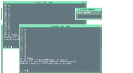
To type text into both node windows simultaneously, click the cursor in the Cluster Console window and type the text. The text does not display in the Cluster Console window. This ensures that both nodes execute the commands simultaneously.


Note - The console windows for both cluster nodes are grouped (the three windows move in unison). To ungroup the Cluster Console window from the node windows, select Options from the Hosts menu, and deselect the Group Term Windows checkbox.


6. In the Cluster Console window, type the following command into both nodes simultaneously:

boot net - install


boot net - You must use spaces before and after the hyphen (-) character in the
"install" command.


The following software is automatically installed on both cluster nodes:

  • Solaris 8 10/01 operating environment
  • VERITAS Volume Manager 3.1.1
  • Sun Cluster 3.0 7/01 and recommended patches
  • Oracle9i Database RAC, version 9.0.1.2

All patches are applied and system files are configured to produce a basic cluster environment. In addition, the Oracle 9i Database RAC software is configured and a sample database is set up.

You may see the following error:

Boot device: /pci@8,700000/network@5,1: File and args:
Timeout waiting for ARP/RARP packet
.
.
.

If so, it is likely that you need to correct one of the following:

  • Naming service conflict--A naming service was selected during the configuration of the management server.
  • No network route--For network environments with a production and an administration network, the two network backbones must be routed so that the cluster nodes can jump start from the management server. If this is the case, you need to temporarily provide two Ethernet cables and connect the eri0 network interfaces on both cluster nodes to the supplied ethernet hub in the Clustered Platform. Once the installation and setup is complete, remove the temporary connections from the ethernet hub and the nodes, and reconnect the cables from the cluster nodes eri0 to the production network.


Note - Press Ctrl+] and send brk to stop the Timeout waiting for ARP/RARP packet errors.


After you execute the boot(1M) command, you should see output as the management server installs and configures the Oracle software. Refer to for an example of the output.

7. Take one of the following actions based on the volume manager product you chose:

8. Log into each cluster node as the superuser (password is abc), and change the default password to a secure password:

# passwd
passwd: Changing password for root
New password: secure-password-choice
Re-enter new password: secure-password-choice

9. Install the Sun Management Center agent.

For instructions, refer to the Sun Management Center documentation.

10. Configure the Sun StorEdge T3 array shared disk storage.

Configure the T3 array volume configuration if you do not plan to use the default T3 configuration. Refer to the T3 documentation that shipped with your Clustered Platform.

Configure the storage using Solstice DiskSuite, then create disk sets, metadevices, and file systems that suit your needs. Refer to the Solstice DiskSuite documentation.

11. Proceed to Finishing Up.


procedure icon  To Configure VERITAS Volume Manager


caution icon

Caution - The following instructions only apply to configurations that are using VERITAS Volume Manager instead of Solstice DiskSuite. Only follow this procedure if you selected to use VERITAS Volume Manager.


Note - You will not see these questions if you chose to install Solstice DiskSuite.


You must have two valid VERITAS license keys (one for each node) to complete this procedure.

1. In the Cluster Console window (cconsole) choose to encapsulate the root disk, and type the pathname of the Jumpstart program:

Do you want Volume Manager to encapsulate root [yes]? yes
 
Where is the Volume Manager cdrom? 
/net/ManagmentServer-ip-address/jumpstart/Packages/VM3.1.1


Note - Ignore references to "cdrom" in the computer output.


2. In each individual node window, enter the license key for that node (obtained from VERITAS) to register your version of VERITAS Volume Manager:


Note - You must enter your own valid VERITAS license keys for the script to complete successfully. A VERITAS license key is made up of 23 digits and is formatted as follows:

1234 5678 1234 5678 1234 567

(This is an example only. Do not use this number.)


Code box showing the volume manager output for node 1. You must enter the license key.

Caution - You must enter valid license keys. If the script detects an error in the license key, the script will not complete successfully.


(For node 1)
Volume Manager installation is complete.
Oct 8 15:34:03 node1 vxdmp: NOTICE: vxvm:vxdmp: added disk array 60020f20000004d60000000000000000
Oct 8 15:34:03 node1 vxdmp: NOTICE: vxvm:vxdmp: added disk array 60020f2000003ea00000000000000000
 
Please enter a Volume Manager license key: node1_VERITAS_license_key


(For node 2)
Volume Manager installation is complete.
Oct 8 15:34:03 node2 vxdmp: NOTICE: vxvm:vxdmp: added disk array 60020f20000004d60000000000000000
Oct 8 15:34:03 node2 vxdmp: NOTICE: vxvm:vxdmp: added disk array 60020f2000003ea00000000000000000
 
Please enter a Volume Manager license key: node2_VERITAS_license_key

3. In the Cluster Console window, wait for the installer script to display the login prompt:

 ================================================================
     Setting up root mirror. This will take approximately 45min's
 
                             Please wait .... 
     ================================================================
     
The system is ready.
node1 console login:

4. In each individual node window, log in to each cluster node as a superuser (password is abc) and change the default password to a secure password:

node1 console login: root
Password: abc
# passwd
passwd: Changing password for root
New password: secure-password-choice
Re-enter new password: secure-password-choice


node2 console login: root
Password: abc
# passwd
passwd: Changing password for root
New password: secure-password-choice
Re-enter new password: secure-password-choice

5. Install the Sun Management Center agent on the cluster nodes.

Installing the Sun Management Center agent enables Sun Management Center to monitor the nodes. For installation instructions, refer to the Sun Management Center 3.0 Installation Guide.

6. Configure the Sun StorEdge T3 array shared disk storage.

Configure the storage using VERITAS Volume Manager. Configure the volumes and file systems to suit your needs. Refer to the VERITAS Volume Manager documentation.


Note - The VERITAS Volume Manager VMSA packages are available on the management server in the /jumpstart/Packages/VM3.1.1 directory. If you want to use the VERITAS GUI, install the VMSA packages with the pkgadd command. Once installed, the Volume Manager man pages will be placed in the /opt/VRTS/man directory. Add this directory to your MANPATH variable to access these pages with the man command.


7. Proceed to Finishing Up.


Finishing Up

You need to perform additional steps depending on your environment. This section contains references to additional steps that may be needed.


procedure icon  To Finish the Installation

1. Install and configure your highly available application(s) for the cluster environment.

For additional details, refer to the manufacturers' documentation that accompanied your highly available application(s).
Refer to the following appendices for additional information about configuring the following software that came with your clustered platform:

2. Establish network automatic failover (NAFO), resource groups, logical hosts, and data services to enable your application(s) under the Sun Cluster 3.0 infrastructure. Refer to the Sun Cluster 3.0 documentation. The path to the Sun Cluster data services is:

/net/sc3sconf1-ms/jumpstart/Packages/SC3.0u1/scdataservices_3_0_ul

NAFO configuration and activation information is in the Sun Cluster 3.0 U1 System Administration Guide (806-7073), Chapter 5, "Administering Cluster Interconnects and Public Networks," section "Administering the Public Network," starting on page 93.


Note - Before you use an editor in a Cluster Console window, verify that the TERM shell environment value is set and exported to a value that emulates the kind of input terminal your are using on the local system.


Note - You can stop the cluster nodes and access the OpenBoot PROM prompt by positioning the cursor in the Cluster Console window and pressing Ctrl+]. This control character sequence displays the telnet prompt. Typing send brk (equivalent to a Stop-A) at the telnet prompt forces access to the OpenBoot PROM prompt.


3. Optionally, enable the Oracle GUI configuration assistant to access the nodes.

Certain Oracle GUI configuration assistants such as dbca and netca require the ability to issue a remote shell (rsh) to the nodes. For this to take place, a .rhosts file must reside in the home directory of each node (for security reasons, the default configuration does not create a .rhosts file). The .rhosts file for each node is populated with the node name of each node, and private interconnect IP addresses (for the local node), followed by the oracle UNIX user name. For security, delete both .rhosts files when you are finished running dbca or netca.
Content for a .rhosts file:
cluster_node1_name oracle
cluster_node2_name oracle
node_private_interconnect_IP_1 oracle
node_private_interconnect_IP_2 oracle


Note - You can run /usr/sbin/ifconfig -a on a node to determine the private interconnect IP addresses.


4. Place the Oracle database into archive log mode.

Choose a location where the Oracle redo log files are copied, and specify the location in the server parameter file. An area on the shared storage device can be used for this purpose. This location should be specified on a UFS file system, not on a raw partition. For more information on these topics, refer to the Oracle documentation.

5. Determine and set up your backup strategy and methods.

For backing-up the Oracle database, if you chose not to place the database into archive log mode, then only offline backups can be performed. In this case, you need to shutdown the instance during the backup, and recovery is only available back to the time of the last offline backup. For more information on these topics, refer to the Oracle documentation.

You are now done installing and configuring the Clustered Database Platform software.


After the Installation

This section contains information about what has been installed and configured on the cluster nodes and what you can do with the software.

Post-Installation Modification of the /etc/hosts File

After the management server finishes installing the software on the nodes, you must update the /etc/hosts file so that it corresponds to the cluster platform network configuration.


procedure icon  To Update the /etc/hosts File

1. On the management server, use a text editor to open the /etc/hosts file.

2. Delete the first two occurrences of the -admin text string (shown highlighted in the following example):

# Physical Hosts (Physical Addresses) 
129.153.47.181 test #Management Server 
129.153.47.71 TC #Terminal Concentrator 
129.153.47.120 node1-admin #First Cluster Node 
129.153.47.121 node2-admin #Second Cluster Node 
10.0.0.1 test-admin #Admin Network 
10.0.0.2 node1 #First Cluster Node admin network 
10.0.0.3 node2 #Second Cluster Node admin network 
10.0.0.4 T3-01 #First T3 Host Name 
10.0.0.5 T3-02 #Second T3 Host Name

3. Append -admin to the two internal administration node names (shown highlighted in the following example):

# Physical Hosts (Physical Addresses) 
129.153.47.181 test #Management Server 
129.153.47.71 TC #Terminal Concentrator 
129.153.47.120 node1 #First Cluster Node 
129.153.47.121 node2 #Second Cluster Node 
10.0.0.1 test-admin #Admin Network 
10.0.0.2 node1-admin #First Cluster Node admin network 
10.0.0.3 node2-admin #Second Cluster Node admin network 
10.0.0.4 T3-01 #First T3 Host Name 
10.0.0.5 T3-02 #Second T3 Host Name

4. Save your changes and quit the editing session.

Post-Installation Removal of the /.rhosts File

For security reasons, when the installation and setup of the cluster platform is complete, remove the root user /.rhosts file on each cluster node to prevent unauthorized access to the nodes. This file is not typically needed after the cluster installation is complete. However, some cluster agents may require the root user to have remote access to the cluster nodes. Refer to the agent documentation for more details.

Oracle9i Packages

The following packages are installed on the cluster nodes:

  • SUNWraco--Oracle 9i RAC, version 9.0.1.2, with Intelligent Agent Patch 1918073
  • SUNWraccf--Scripts to configure RAC database at node install time

Starter Database

The starter database is configured with the default Oracle passwords. For the sys user, the password is change_on_install. For the system user, the password is manager. You should change these passwords by using the alter user command in SQL*Plus.

Database Recovery

You should place each starter database provide with the Clustered Database Platform into archive log mode. You must choose a location to which the redo log files may be copied and to specify it in the server parameter file. For Oracle9i RAC, you must set it up on each instance.

Backup Method

You should choose a backup method to be performed on a regular basis, such as offline or online. You must provide the scripts. If you choose not to place the database into archive log mode, then only offline backups can be performed. An offline backup involves a shutdown of the instance, which means that the recovered data would only reflect the last offline backup. For more information on these topics or to read about Oracle Recovery Manager, refer to your Oracle software documentation.

Redo Log Groups

The RAC redo log files are not set up in redo log groups. You can, however, create the redo log groups and add the RAC redo log files so that each group acts as mirrors for redundancy. Use the ALTER DATABASE ADD LOGFILE MEMBER command to add the RAC redo log files to the groups.

If you add the RAC redo files and the database is placed into archive log mode, the Archiver background process can take advantage of the multiple copies to perform pre-fetching of redo log blocks from each group member in a round-robin fashion. For more information, refer to your Oracle software documentation, as well as Doc. ID 45042.1 on http://metalink.oracle.com. (You must be registered to use this site.)

Operation Instructions

You can access operation instructions in the Clustered Database Platform 280/3 system documentation and the Oracle documentation (see Clustered Database Platform Documentation).