| Cluster Platform 15K/9960 System Site Planning Guide |
| Cluster Platform 15K/9960 System Site Planning Guide |
| C H A P T E R 5 |
|
Network Planning |
This chapter contains information about the cabling connections for the Cluster Platform 15K/9960 system. It also includes system setup tables that you must complete before you attempt to install the system.
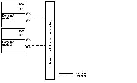
The Cluster Platform 15K/9960 system requires 10/100BASE-TX Ethernet connections on the customer network for each Sun Fire 15K server.
Each cluster node uses a Sun Quad FastEthernet interface (qfe0) to connect to the public network. Port qfe4 is reserved as the network adapter failover (NAFO) interface for qfe0 on both cluster domain nodes. A qualified service technician must configure network failover (NAFO) interfaces using the pnmset(1M) command.
|
Note - Interfaces qfe2, qfe3, qfe5, qfe6, and qfe7 are available to expand network services. The qfe1 interface is reserved for the internal administration network. |
The public network uses a 10/100BASE-T network hub to provide access to the domains. The hub is customer supplied. FIGURE 5-1 shows the layout of the public network.
|
Note - In the following diagram, the external public hub can be a switch or a hub. |
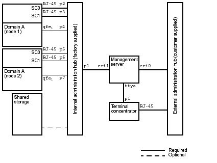
The administration networks use a 10/100BASE-T network hub to provide access to the system controllers, domains (nodes), the shared storage, and the customer Intranet. FIGURE 5-2 shows the layout of the administration networks.
|
Note - In the following diagram, the external public hub can be a switch or a hub. |
FIGURE 5-2 Administration Networks
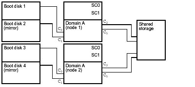
The storage connections enable the domains to have access to the shared storage and to the boot disks in the expansion cabinet. FIGURE 5-3 shows the layout of the storage connections.
FIGURE 5-3 Storage Connections
The serial connections enable the terminal concentrator to have access to the system controllers. FIGURE 5-4 shows the layout of the serial connections.
FIGURE 5-4 Serial Connections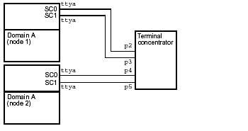
Host names, networks, internet protocol (IP) addresses, and subnet masks for the Cluster Platform 15K/9960 system are required.
Configuration of the system controllers and the installation of the operating system on the domains will also require host names, IP addresses, and subnet masks. Multiple user communities may also be involved. The tables that follow are designed to help organize this information before the installation.
The Sun Fire 15K server requires a platform name. The platform name, globally unique within the network, is a logical name given to an entire system and does not correspond to any host on the network. These names get set when you configure the system controllers. Use TABLE 5-1 to record the platform name for your records.
Host names and IP addresses are also required for the domain connections to a user community. Use TABLE 5-2 to record the domain settings. These values are set when you configure the system controllers.
The subnets for the internal networks are fixed. Because I1, which is the domain to system controller management network (that is, MAN), and I2, which is the system controller to system controller management network, are not routed, the IP networks can be taken from the IP private pool. These networks should be set up using automatic assignment of host names and IP addresses. The networks should be unique within the customer network.
Enter the IP network address and subnet mask in TABLE 5-4. The subnet mask must be unique within the network. The system controller can connect only to one user community. These addresses are set when you configure the system controllers.
IP addresses are required for every interface on the system controller (SC) that is cabled to a user community. Both SCs have one built-in Ethernet port (labeled "Ethernet") cabled, and the other port ("Ext Ethernet") is not used in this configuration.
The following table contains the user community and IP address for the SCs. These settings are set when you configure the system controllers.
Additionally, a logical interface is required for the SCs for each user community. Logical interfaces are only present on the main SC. SC pathgroup-specific IP addresses are also required when using an HA configuration (refer to the Sun Fire 15K Site Planning Guide for more information). Use the following table contains to record the logical interfaces. These interfaces are set when you configure the SCs.
|
Note - The logical and pathgroup-specific IP address for a community must use the same IP network and subnet as the physical NIC(s) in that community. |
You will need to provide the name, IP address, subnet mask, and broadcast address for the terminal concentrator. Use the following table to record the values.
You will need to provide the following values during the management server configuration. Use the following table to record the values.
You will need to provide the following values for node 1 during the management server configuration. Use the following table to record the values.
You will need to provide the following values for node 2 during the management server configuration. Use the following table to record the values.
You will need to provide the following values for the cluster interconnect during the management server configuration. Use the following table to record the values.
| Cluster Platform 15K/9960 System Site Planning Guide | 816-3537-10 |
Copyright © 2002, Sun Microsystems, Inc. All rights reserved.