| A P P E N D I X A |
|
Loopback Connectors |
Loopback connectors are designed for the testing of communication ports. They take the form of either a single plug or a port-to-port cable with some communication connections shorted (looped-back).
The following table depicts the pin assignments for most loopback plugs and cables that may be used when testing a system.
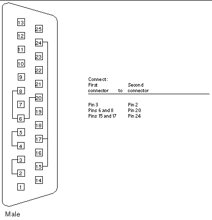
The RS-232 and RS-423 single-port loopback plug is a specially wired male
DB-25 connector. It is plugged in to a serial port in the back of the system under test.
FIGURE A-1 25-pin RS-232 Loopback Plug Wiring Diagram
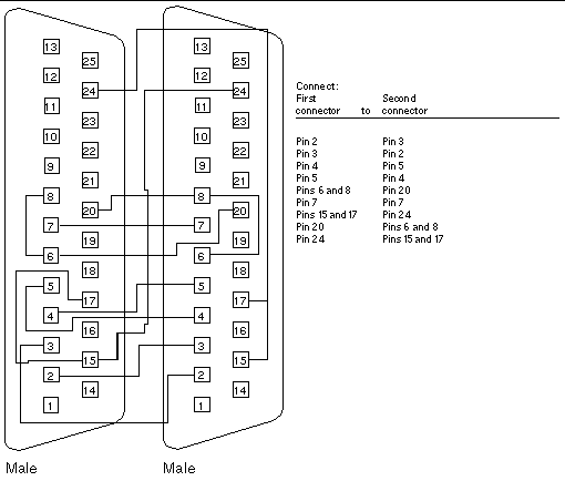
Use these wiring instructions for 25-pin RS-232 and RS-423 port to 25-pin RS 232 and RS 423 port loopback cables (two DB-25 connections). It is plugged into a pair of serial ports in the back of the system under test. Both connectors are male.
FIGURE A-2 25-pin RS-232 Port-to-Port Loopback Cable Wiring Diagram
Use these wiring directions for 8-pin round DIN RS-232 port to RS-423 to 8-pin round-DIN RS-232 and RS-423 port loopback cable. Both connectors are male.
FIGURE A-3 8-Pin to 8-Pin Loopback Cable Wiring Diagram
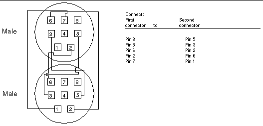
Pin 8, Receive clock In (DD), remains unconnected.
Use these wiring directions for male 8-pin round-DIN RS-232 and RS-423 single-port loopback plugs.
FIGURE A-4 8-Pin Loopback Plug Wiring Diagram
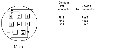
Pin 8, Receive Clock In (DD), remains unconnected.
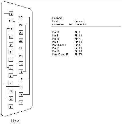
Use these wiring directions for a 25-pin Port A to Port B loopback plug for most systems.
FIGURE A-5 Port A-to-Port B Loopback Plug Wiring Diagram
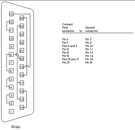
If your system has a single communication port to connect it to peripherals, use these wiring instructions for making a male 25-pin loopback plug for that communication port.
FIGURE A-6 Port A-to-A, Port B-to-B Loopback Plug Wiring Diagram
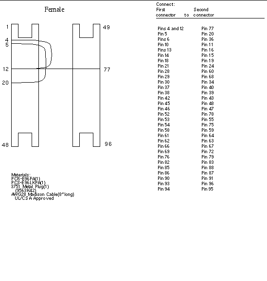
This 96-pin connector can be ordered from Sun (part number 370-1366).
FIGURE A-7 96-Pin Female Loopback Connector Wiring Diagram
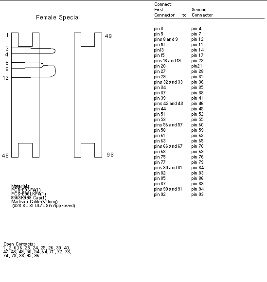
This 96-pin connector can be ordered from Sun (part number 370-1381).
FIGURE A-8 96-Pin Female Special Loopback Connector Wiring Diagram
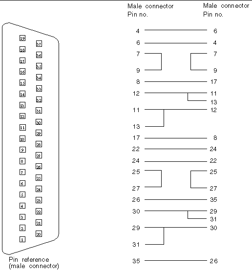
Use these wiring instructions for a loopback cable for two 37-pin RS-449 synchronous ports.
FIGURE A-9 37-Pin RS-449 Loopback Cable Wiring Diagram
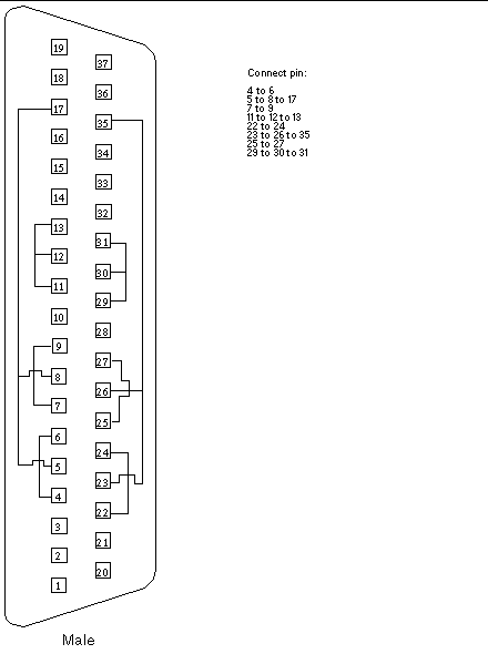
Use these wiring instructions for making a male 37-pin RS-449 loopback plug. This connector is also available from Sun (part number 530-1430).
FIGURE A-10 37-Pin RS-449 Loopback Plug Wiring Diagram
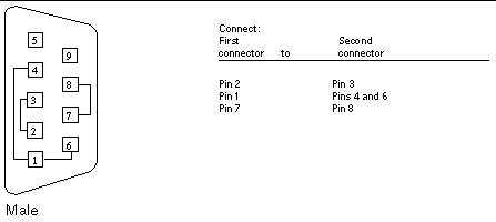
Use these wiring instructions for male 9-pin RS-232 and RS-423 single-port loopback plugs.
FIGURE A-11 9-Pin Male Single-Port Loopback Plug Wiring Diagram
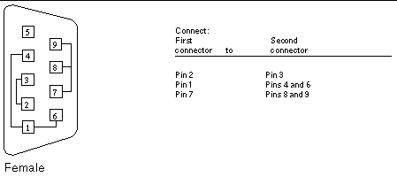
Use these wiring directions for female 9-pin RS-232 and RS-423 single-port loopback plugs. Use this loopback plug with the pcmciatest.
FIGURE A-12 9-Pin Female Single-Port Loopback Plug Wiring Diagram
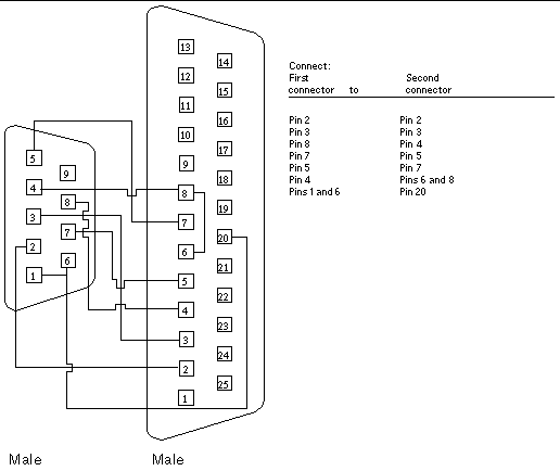
Use these wiring instructions for a 9-pin RS-232 and RS-423 port to 25-pin RS-232 and RS 423 port loopback cables. Both connectors are male.
FIGURE A-13 9-Pin to 25-Pin Port-to-Port Loopback Cable Wiring Diagram
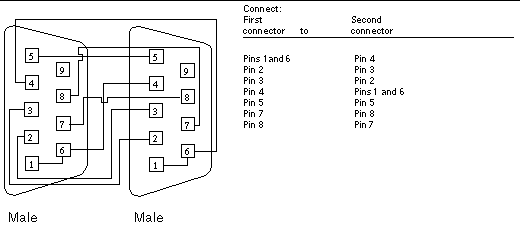
Use these wiring instructions for 9-pin RS-232 and RS 423 port to 9-pin RS-232 and RS-423 port loopback cables. Both connectors are male.
FIGURE A-14 9-Pin to 9-Pin Port-to-Port Loopback Cable Wiring Diagram
Please note that this cable has no Sun part number assigned to it.
Using two standard RJ-45 connectors, and connect pin 1 to pin 1, pin 2 to pin 2, and so on, for all pins. This loopback is a "straight-through" connection.
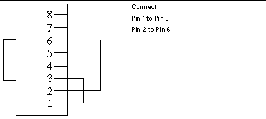
Use the following wiring instructions for standard RJ-45 connectors for Fast Ethernet. This loopback cable is used in netlbtest for eri devices.
FIGURE A-15 Twisted-Pair Ethernet (TPE) Loopback Cable Wiring Diagram for Fast Ethernet
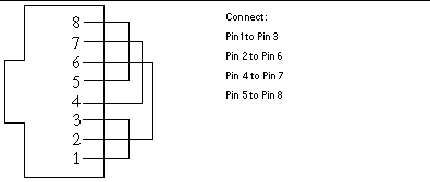
Use the following wiring instructions for RJ-45 connectors for Gigabit and 10/100 Ethernet. This loopback cable is used in netlbtest for Gigabit and 10/100 devices.
FIGURE A-16 TPE Loopback Cable Wiring Diagram for Gigabit and 10/100 Ethernet
Copyright © 2002, Sun Microsystems, Inc. All rights reserved.