


Alan Charlesworth
(Author's
email addresses are: Firstname.Lastname@west.sun.com)
Sun Microsystems, Inc.
![]()
The compute performance of microprocessors has been improving at a rate of 55% per year, while memory access speeds have been improving by only 7% per year [3]. Ten years ago, floating-point operations were considered quite expensive, often costing 10 times as much as a cache miss. Today the situation is dramatically reversed, with the fastest processors able to perform 200 or more floating-point operations in the time required to service a single cache miss [4].
Our challenge as system architects is to scale system memory bandwidth to match the increasing abilities of microprocessors, and to reduce memory latency as much as possible. The designer's bag of tricks includes: multiple outstanding cache misses, split-transaction buses, separate address and data paths, 16-byte-wide data paths, and 100 MHz system clocks.
To plot processor and system interconnect trends, we use the Stream [5] benchmark -- which is the only available memory benchmark with a large number of posted results. Stream measures the performance of four loops: vector copy, vector scale, vector add, and vector triad. Each loop has a length of 2 million elements per processor. Stream is available in either Fortran or C.
Bandwidth. We plot the average of the four Stream loops, as adjusted to include the extra write-allocate traffic on cache-based systems that is caused by the stores in the vector loops. When the first 8-byte store-miss happens to a cache block, the processor must read the entire cache-coherency unit (typically 64 bytes) from memory -- even if the block will be overwritten by later stores.
Total bandwidth = (Copy_Bandwidth · 3/2 + Scale_Bandwidth · 3/2 + Vadd_Bandwidth · 4/3 + Triad_Bandwidth · 4/3) / 4
Latency. Our latency estimate is the time per Stream memory access, including both reads and writes:
Latency (ns) = Cache block size (bytes) / Total bandwidth (MBps) · 1000 · Number of processors
Since Stream is vectorizable, these latencies are lower than the pointer-chasing latencies from lmbench[6], because today's microprocessors can maintain multiple outstanding cache misses on vector code. We couldn't use lmbench latency for this analysis, because there are too few results posted, and because that benchmark is limited to single-processors, and we wish to plot multiprocessor latencies.
Figure 1 shows the highest-bandwidth single-processor Stream results from each microprocessor family over time. The bandwidths in Figure 1A are quadrupling every three years. Sun's best single-processor Stream bandwidth has increased by 8.5x in 4 years: from 70 MBps in spring 1993 to 450 MBps in the spring of 1997.
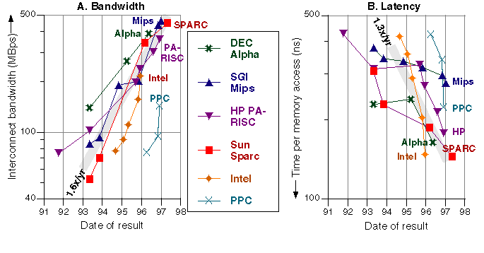
The latencies in Figure 1B have come down by a factor of 2.7x over the period -- due to faster buses, and the growing ability of processors to overlap multiple cache misses.
Figure 2 shows the highest-bandwidth multiprocessor results over time from each of the four symmetric multiprocessor (SMP) vendors. It used to be said that SMPs couldn't scale. Figure 2A shows that bandwidths have more than quadrupled in each of the past four years -- as systems have expanded from one to 64 processors. Sun's best multiprocessor Stream bandwidth has grown from 70 MBps in late 1993, to 9,500 Mbps this year on the Starfire -- a factor of 132x in 3.25 years.
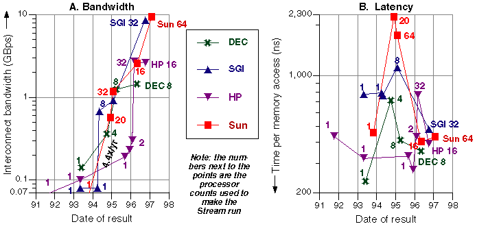
The latencies in Figure 2B show an interesting trend. The initial multiprocessor results from each vendor (circa 1995) show an upward jump in latency, reflecting the difficulties of interconnecting many cache-coherent processors. The second-generation SMP results (circa 1997) show major improvement in latencies. Newer processors can keep more cache misses outstanding, newer systems use routers to provide greater bandwidth, and interconnect protocols have been streamlined.
With 64 processors, the Starfire Ultra 10000 is the apex of Sun's SMP product pyramid. The family extends down through the 6-30 processor Ultra 3000-6000 servers [14], the four processor Ultra 450 workgroup server [13], and the single-processor Ultra 30 workstation [12].
All Sun workstations and servers use the same Ultra Port Architecture (UPA) [7] interconnect protocol. This is Sun's third-generation SMP interconnect architecture, following the second-generation XDBus and the first-generation MBus. The UPA does writeback MOESI (exclusively modified, shared modified, exclusively clean, shared clean, and invalid) coherency on 64-byte-wide cache blocks. It is a packet-switched protocol, with separate address and 18-byte-wide data lines, which includes two bytes of error-correcting code (ECC). The highest system clock rate so far is 100 MHz, which yields a peak UPA_databus rate of 1,600 MBps.
UPA implementations maintain a set of duplicate coherence tags for each cache in the system, and perform fast SRAM tag lookups in parallel with memory reads. All of the UPA implementations provide uniform memory-access times (UMA), regardless of data placement.
The processor used in Sun's UPA systems is the UltraSPARC-II [11]. As of this writing, it has a clock rate of up to 300 MHz and an external cache size of up to 4 MB. The processor can do a maximum of two floating-point operations per clock, which at this clock rate is 600 Mflops. Its performance is 12.1 SPECint95 and 18.3 SPECfp95 in an Ultra 30 workstation with a 2 MB cache [9]. The processor is mounted on a module along with cache SRAMs and two UltraSPARC Data Buffer (UDB) chips. The UDBs generate ECC bits when they write to the UPA_databus, and check ECC when they read from the UPA_databus.
Sun has developed UPA implementations to fit the needs of small, medium, and large systems.
| Size | UPA implementation | System | Max system boards | Max processors | Max memory bandwidth |
lmbench latency |
|---|---|---|---|---|---|---|
| Small |
Central system controller 2 / 4-port data switch |
Ultra 30 Ultra 2 Ultra 450 |
1 |
1 2 4 |
1,800 MBps | 240 ns |
| Medium |
Gigaplane Address bus between distributed controllers, 32-byte-wide interboard data bus |
Ultra 3000 Ultra 5000 Ultra 6000 |
4 8 16 |
6 14 30 |
2,667 MBps | 310 ns |
| Large |
Gigaplane-XB 4 interleaved point-to-point address routers, 16x16 interboard data crossbar |
Starfire Ultra 10000 | 16 | 64 | 10,667 MBps | 550 ns |
By optimizing separate UPA implementations for low, middle, and high-end systems we have created a product family with very good latencies and bandwidths across the range of 1 to 64 processors. When one cabinet is not enough, Sun has High Availability (HA) and Parallel Database (PDB) cluster products -- which are beyond the scope of this paper.
To fit at the top of the Ultra server family, we set three primary product goals for the Starfire:
1. Scale 4x larger in bandwidth.
2. Increase system flexibility.
3. Improve system reliability, availability, and serviceability (RAS).
We made the following implementation choices:
The hardest part of scaling up an SMP system is to increase its coherency bandwidth. Providing more data bandwidth is easy in comparison. To quadruple the snooping bandwidth over the Ultra 6000, we chose to interleave four snoop buses. We had done this before on the 64-processor CS6400, our XDBus-generation system. Each address bus covers 1/4 of the physical address space. The buses snoop every-other cycle, and update the duplicate tags in the alternate cycles. At an 83.3 MHz clock, Starfire's coherency rate is 167 million snoops per second. Multiplied by the UPA's 64-byte cache line width, this is enough for a 10,667 MBps data rate.
To match the snooping rate, we chose a 16x16 inter-board data crossbar, with the same 18-byte width as the UPA_databus.
We wanted to keep any failures on one system board from affecting other system boards, and to be able to dynamically partition the system. To electrically isolate the boards, we used point-to-point router ASICs for all of the interconnect -- data, arbitration, the four address buses, and JTAG. Also, across a large cabinet, point-to-point wires can be clocked faster than bused signals.
The natural place to mount the router ASICs was on the centerplane, which is physically and electrically in the middle of the system.
The SSP is fundamental to our RAS strategy. It provides a known-good system that is physically separate from Starfire. We connected it via Ethernet to Starfire's control boards, where it has access to JTAG hardware information.
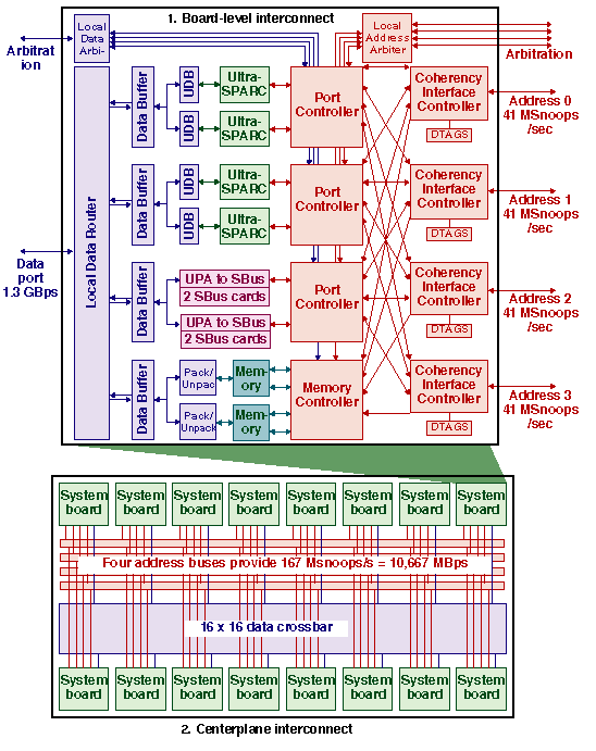
Like most multi-board systems, Starfire has a two-level interconnect, which is shown in Figure 3:
1. On-board interconnect -- conveys traffic from the processors, SBus cards, and memory to the off-board address and data ports.
2. Centerplane interconnect -- transfers addresses and data between the boards.
Memory accesses always go across the global interconnect, even if the requested memory location is physically on the same board. Addresses must go off board to accomplish global snooping. Data transfers are highly pipelined, and local shortcuts to save a few cycles would have unduly complicated the design. Starfire, like the rest of the Ultra server family, has a uniform memory-access time that is independent of the board where memory is located.
Address transactions take two cycles on the address interconnect. The two low-order cache-block address bits determine which address bus to use.
Data packets take four cycles on the data interconnect. In the case of a load-miss, the missed-upon 16-bytes are sent first. The Starfire Data Buffers provide FIFOs for centerplane data transfers. The local and global routers are not buffered, and transfers take a fixed 8 clocks from buffer to buffer.
We illustrate Starfire's interconnect operation with the example of a load-miss to memory:
| Phase | Steps | Clocks |
|---|---|---|
| Send address and establish coherency |
1. Processor makes a request to its Port Controller (PC). 2. PC sends the address to a Coherency Interface Controller (CIC), and sends the request to the Local Address Arbiter (LAARB). 3. CIC sends the address through the Global Address Bus to the rest of the CICs. 4. All CICs relay the address to their Memory Controllers. 5. All CICs snoop the address in their Duplicate Tags. 6. All CICs send their snoop results to the Global Address Arbiter (GAARB). 7. GAARB broadcasts the global snoop result. 8. Memory is not aborted by a CIC, because the snoop did not hit. |
13 net (8 more are overlapped with memory) |
| Read from memory |
1. Memory Controller (MC) recognizes that this address is for one of its memory banks. 2. MC orchestrates a DRAM cycle, and sends a request to the Local Data Arbiter (LDARB). 3. Memory sends 72 bytes of data to the Unpack unit. 4. Unpack splits the data into four 18-byte pieces. 5. Unpack sends data to the Starfire Data Buffer (SDB) to be buffered for transfer. |
13 |
| Transfer data |
1. SDB sends data to the Local Data Router (LDR). 2. Through the LDR to the centerplane crossbar. 3. Through the centerplane crossbar to the receiving board's LDR. 4. Through the receiving LDR to the processor's Starfire Data Buffer. 5. SDB sends data to the Ultra Data Buffer (UDB) on the processor module. 6. UDB sends data to the processor. |
12 |
The total is 38 clocks (468 ns) -- counting from the cycle when the address request is sent from the processor through the cycle when data is delivered to the processor.
For more technical information on the Starfire interconnect operation and implementation, see [1].
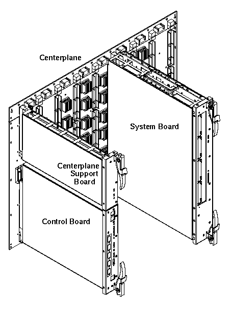
Starfire is packaged in a cabinet 70" tall x 34" wide x 46" deep, as shown in Figure 4. Inside the cabinet are two rows of eight system boards that mount on either side of a centerplane. Starfire is our fourth generation of centerplane-based systems.
Besides the card cage, power, and cooling, the cabinet has room for three disk trays. The rest of the peripherals are housed separately in standard Sun peripheral racks.
Power. Starfire does two levels of power conversion. Up to eight N+1 redundant bulk supplies convert from 220 VAC to 48 VDC, which is then distributed to each board. Supplies on each board convert from 48 VDC to 3.3 and 5 VDC. Having local power supplies facilitates the hot swap of system boards while the system is running.
Cooling. Starfire uses 12 hot-pluggable fan trays --þhalf above and half below the card cage. Fan speed is automatically controlled to reduce acoustic noise in normal environmental conditions.
The centerplane holds the 20 address ASICs and 14 data ASICs that route information between the 16 system-board sockets. It is 27" wide x 18" tall x 141 mils thick, with 14 signal layers and 14 power layers. The net density utilization is nearly 100%. Approximately 95% of the nets were routed by hand. There are 14,000 nets, approximately two miles of wire etch, and 43,000 holes.
The board spacing is 3" to allow enough air flow to cool the four 45-watt processor modules on each system board. Signal lengths had to be minimized to run a 10 ns system clock across 16 boards. The distance between adjacent boards (front-to-back) is approximately 1". The maximum etched wire length is approximately 20". We did extensive crosstalk analysis, and developed and implemented a novel method for absolute-crosstalk minimization on long minimally-coupled lines.
Clock sources are distributed through the centerplane to each system board ASIC. Skew between clock arrivals at each ASIC is minimized by routing all traces on identical topologies.
We used uni-directional point-to-point source-terminated CMOS to implement the 144-bit-wide 16 x 16 data crossbar, and the four 48-bit-wide address-broadcast routers. The system has been designed and tested to run at 100 MHz at worst-case temperatures and voltages. However, the system clock must be 1/3 or 1/4 of the processor clock. As of this writing, the processor clock is 250 MHz, so the system clock is 250/3 = 83.3 MHz.
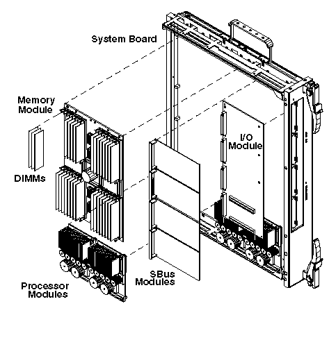
The system board, shown in Figure 5, holds six mezzanine modules on its top side: the memory module, the I/O module, and four processor modules. The bottom side of the system board has nine address ASICs, nine data ASICs, and five 48-volt power converters. The board is 16" x 20" with 24 layers.
Starfire uses the same UltraSPARC processor module as the rest of Sun's departmental and data center servers. As of this writing, the server modules have a 250 MHz processor with 4 MB of external cache.
The memory module contains four 576-bit-wide banks of memory composed of 32 standard 168-pin ECC DIMMs. It also has four pack/unpack ASICs on it. The memory module contains 1 GB of memory with 16-Mbit DRAMs, and 4 GB of memory with 64-Mbit DRAMs.
The current I/O module interfaces between the UPA and two SBuses, and provides four SBus card slots. Each SBus has an achievable bandwidth of 100 MBps.
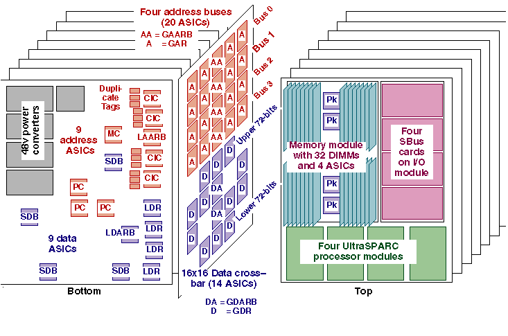
We designed seven unique ASIC types. Six of them (PC, MC, CIC, XARB, GDARB, and SDB) implement an entire functional unit on a single chip. The seventh ASIC (XMUX) is a multiplexor part which is used to implement the local and global routers, as well as the pack/unpack function. The ASICs are fabricated in 3.3 volt, 0.5 micron CMOS technology. The largest die size is 9.95 x 10 mm with five metal layers. They are all packaged in 32 x 32 mm Ceramic Ball Grid Arrays (CBGAs) with 624 pins.
In addition to the ECC for data that is generated and checked by the processor module, the Starfire ASICs also generate and check ECC for address packets. The Starfire Data Buffer chips check data-packet ECC along the way through the interconnect to help isolate faults.
If an UltraSPARC module, DIMM, SBus board, memory module, I/O module, system board, control board, centerplane support board, power supply, or fan fails -- the system attempts to recover without any service interruption. Later, the failed component can be hot swapped out of the system, and can be replaced while the system is still on line.
The customer can optionally configure a Starfire to have 100% hardware redundancy of configurable components: control boards, support boards, system boards, disk storage, bulk power subsystems, bulk power supplies, cooling fans, peripheral controllers, and System Service Processors. The centerplane can operate in a degraded mode in the event of a failure there. If one of the four address buses fails, the remaining buses can be used to access all the system resources. The data crossbar is divided into separate halves, so it can operate at half-bandwidth if an ASIC fails.
A fully redundant system can always recover from a system crash, utilizing standby components or operating in degraded mode. Automatic System Recovery (ASR) enables the system to reboot immediately following a failure, automatically disabling the failed component. This approach prevents a faulty hardware component from causing the system to crash again, or from keeping the entire system down.
Dynamic System Domains make Starfire unique among Unix servers. The system can be dynamically subdivided into multiple computers, each consisting of one or more system boards. System domains are similar to partitions on a mainframe. Each domain is a separate, shared-memory SMP system that runs its own local copy of Solaris. Because individual system domains are logically isolated from other system domains, any hardware and software errors are confined to their respective domain, and do not affect the rest of the system. This allows a system domain to be used to test updates to Solaris, device drivers, or new application software without impacting production usage.
System domains are configured to have their own disk storage and networking. Administration of each system domain is done from the System Service Processor (SSP) that services all the domains. The system administrator may create domains dynamically without impacting work in progress on the system.
Dynamic System Domains may be used for many purposes that enable the site to manage the Starfire resources effectively:
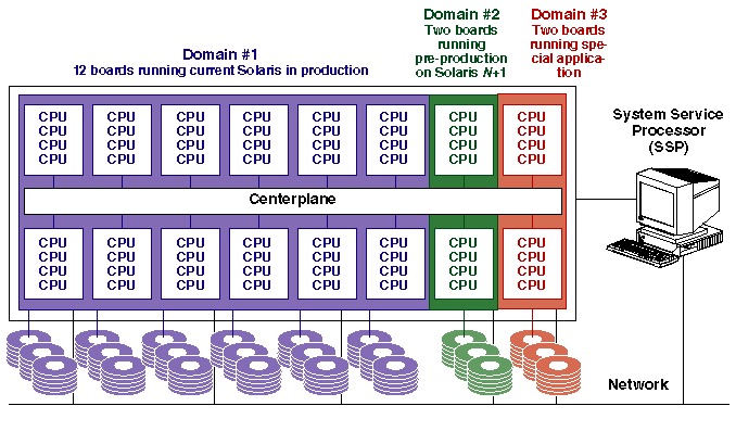
Figure 6 shows an example of how a Starfire may be divided into domains. Domain #1 is a 12-board (48 processor) production domain running the current release of Solaris. Domain #2 is a two-board (8 processor) domain being used to check out an early version of the next release of Solaris. Domain #3 is a two-board (8 processor) domain running a special application -- for instance proving that the application is fully stable before allowing it to run on the production domain #1. Each domain has its own boot disk and storage, as well as its own network connection.
Multiple domains can optionally be combined into a domain group. Domain groups are used for memory-based fast networking between member domains. Hardware faults propagate to all the domain-group members, but software failures only bring down the domain in which they occurred. Domains outside the group are unaffected by failures within a domain group.
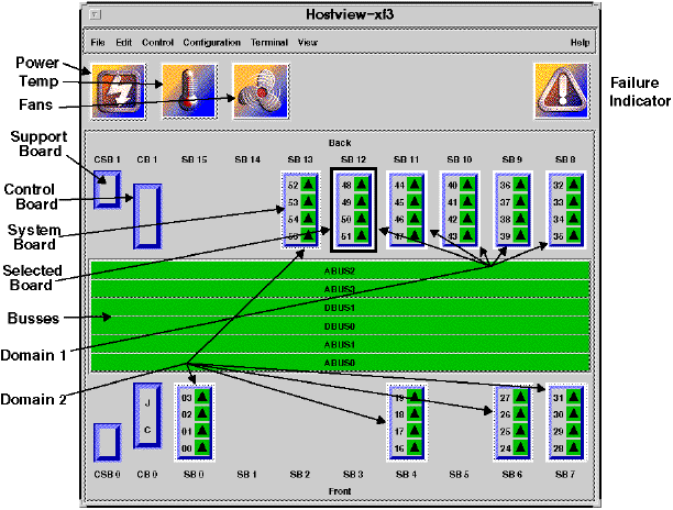
The System Service Processor (SSP) is a SPARC workstation that runs standard Solaris plus a suite of diagnostics and management programs. These include Power-On Self-Test (POST), hostview, and Network Console utilities developed for the Starfire system. The SSP enables the operator to monitor and control the system. Figure 7 shows the Starfire hardware and domain status in hostview's main screen.
These programs sequence the boot process, assist in configuration decisions, manage Dynamic System Domains, monitor environmental conditions, help the system recover from interrupts, and can send diagnostic information to SunService. Using Network Console, the SSP can be remotely accessed to facilitate system administration functions of the Starfire system. A second SSP can be optionally configured as a hot spare. The SSP is connected via Ethernet to a Starfire control board. The control board has an embedded control processor which interprets the TCP/IP Ethernet traffic and converts it to JTAG control information.
Dynamic reconfiguration (DR) allows the system administrator to add and delete system boards from system domains while the system is running. DR is divided into two phases: attach and detach.
Attach connects a system board to a domain, and is used to perform online upgrades, to redistribute system resources for load balancing, or to reintroduce a board after it has been repaired. Attach diagnoses and configures the candidate system board so it can be introduced safely into the running Solaris operating system. There are two steps:
1. The board is added to the target domain's board list in the domain configuration files on the SSP. Power-On Self-Test (POST) is executed, which tests and configures the board. POST also creates a single-board domain group that isolates the candidate board from other system boards on the centerplane. The processors are moved from a reset state into a spin mode, preparing them for code execution. The centerplane and board-level domain registers are configured to include the candidate board in the target domain.
2. When these operations are complete, the Solaris kernel is presented with the board configuration. Solaris is now aware of the configuration, but has not yet enabled it. At this juncture, status information is presented to the operator, who can either complete the attach or abort. After the operator authorizes completion, Solaris performs the final steps needed to start up the processors, adds the memory to the available page pool, and connects any on-board I/O devices or network connections. The operator is notified, and the candidate board is now actively running the workload in the domain.
System boards are detached to reallocate them to another domain, or to remove them for upgrade or repair. All current activity on the system board must be terminated or migrated to other system boards. This includes process execution, memory data, I/O devices, and network connections. This is done in two steps:
1. All pageable memory is flushed to disk, removing it from use by Solaris. Kernel memory is remapped to other boards. Free pages are locked to prevent further use. As detach proceeds, all network devices present on the system board are disabled, and file systems are unmounted or switched to alternate paths to other boards. Processors are taken off-line.
2. The operator can still abort the removal of the board from the system, so the board can continue operation. Otherwise, the detach is committed, and the system board is now available for attachment to another domain or for physical removal from the system.
Once a board has been detached, it can be powered down and physically removed from a running system by a certified service provider. Conversely, a new, repaired, or upgraded board can be physically inserted into a running system, and powered-on in preparation for doing an attach.
Domain protection is implemented at two levels: on the centerplane arbiters, and in the Coherency Interface Controllers on each board.
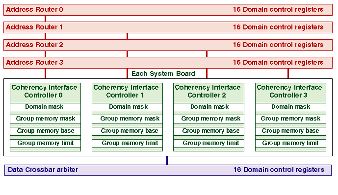
The global arbiters do the first-level filtering that identifies all the boards in a domain group. Each global arbiter contains a 16 x 16 bit set of Domain Control Registers. There is a register for each system board that, when the bits are set to one, establishes the set of system boards in the domain group of that particular board.
A board must always list itself in its own domain group to obtain centerplane arbitration services. At times it is desirable to remove the listing of a system board from its own register to deconfigure that board for removal. After a bus transaction request is granted, the Global Address Arbiter examines the source board domain group register. Only boards within the domain group will receive a valid signal. If a valid signal is received, the board will look at the bus information and further decode it. The Global Address Arbiter similarly filters all BusHold and Error signals so that they are only propagated to boards in the domain group of the originating board. The domain control registers are readable and writable only from the SSP via JTAG.
Local filtering removes inter-domain addresses that are outside the group-memory ranges of a domain group. All four Coherency Interface Controllers on a system board have identical copies of the following registers:
The group mask, base, and limit registers are readable and writable via by the operating system through the control and status address space.
Space permits discussion of only a few performance benchmarks.
Latency and bandwidth are defined the same as they were in Section 1.1. For each of the four SMP families, we plot the total Stream bandwidth for successively larger system configurations -- moving to the next larger family member when interconnects become saturated. For all families, the lowest latency is provided by a workstation.
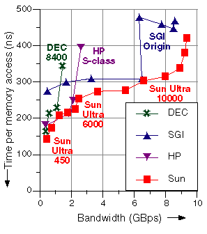
For the Sun server family, the progression in Figure 9 is the Ultra 450 workgroup server for one and two processors, the Ultra 6000 server up to its 2.6 GBps bandwidth, and then the rest of the way with the Ultra 10000 server. This combination delivers the lowest latency across the bandwidth spectrum.
The discontinuity in the SGI Origin curve at 16 processors is caused by dual-processor nodes sharing bandwidth on larger systems. The Stream benchmark is favorable to nonuniform memory-access (NUMA) systems like the SGI Origin and HP S/X class, since the vector loops are completely parallel, and the data sets are small enough to fit in the local memories on those systems. Stream does not do global or shared accesses, which would benefit from uniform memory access implementations like those of the Ultra server family.
Solving large sets of equations is the numerically-intensive heart of many scientific and engineering applications, including structures, fluids, heat flow, electromagnetics, acoustics, visualization and economic modeling. Increased computer power allows higher resolution and more sophisticated modeling, resulting in improved designs and products.
One of the most computationally challenging problems arises in radar cross-section analysis, which is used in the design of radar-evading stealth vehicles. Simulating these electromagnetic fields produces a full matrix requiring multiple solutions, one for each viewing angle. Higher radar frequencies require finer models, which produce very large matrices.
We tested Starfire on one-day's worth of out-of-core matrix factoring: a 90,112 x 90,112 double-precision complex matrix, with 3,600 right-hand sides. Starfire sustained 23.7 Gflops for this 25.6-hour factoring and solving job, performing a total of 2 x10^15 floating-point operations. The system had 16 GB of memory and five disk trays (140 GB) to hold the matrix -- which was stored on disk and processed in blocks small enough to fit into memory buffers. Sixty-three processors did the computing, and one processor managed the asynchronous disk I/O. Starfire sustained 74% of its peak performance over the day-long run. The system cost was $117 per delivered Mflop.
On the Linpack N=1000 matrix, the Ultra 6000 has the highest performance of any SMP system at 4,755 Mflops [2]. The matrix in Linpack N=1000 occupies only 8 MB of memory, and so demands a low memory latency to be computed on in parallel. Because of its high-speed bus architecture, the Ultra 6000 has the lowest memory latency of any large SMP.
The TPC Benchmark D (TPC-D) models a decision support environment where complex ad hoc business-oriented queries are submitted against a large database. The queries access large portions of the database and typically involve one or more of the following characteristics: multi-table joins, extensive sorting, grouping and aggregation, and sequential scans.
Decision support applications typically consist of long and often complex read-only queries that access large portions of the database. Decision support databases are updated relatively infrequently. The databases need not contain real-time or up-to-the-minute information, as decision support applications tend to process large amounts of data which usually would not be affected significantly by individual transactions.
TPC-D comes in a range of sizes: 1 GB, 30 GB, 100 GB, 300 GB, and 1 TB. It has three metrics:
Figure 10 shows all ten of the 300 GB results [18] as of this writing. By sorting the results by database vendor, we can examine the performance of different system architectures running the same database software. Currently, Informix makes the best TPC-D performance, but as with most benchmarks, the vendor leap-frogging will continue.
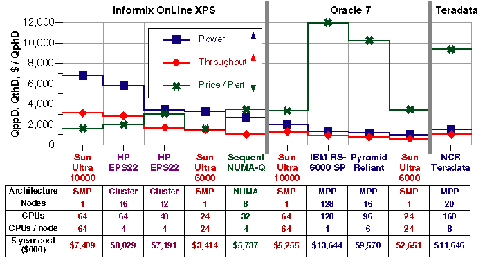
The Ultra 10000 has the best Informix power and throughput, and is second to the Ultra 6000 in price-performance. The Ultra 10000 leads in all three categories for Oracle, and the Ultra 6000 is second in price-performance. Sun's results show the efficiency of large SMP systems for decision support workloads relative to NUMA, MPP, and cluster alternatives. For more details, see [10].
In June 1997, the Starfire set power, throughput, and price-performance records for the 1 terabyte size TPC-D. (NCR has recently surpassed Starfire's power and throughput records with a 256-processor MPP configuration costing over $15 million. Starfire still holds the 1 TB price-performance record.)
The 1 TB size of TPC-D represents commercial supercomputing. The Starfire was configured with 64 processors, 64 GB of memory, and 598 disk drives. The 5.4 TB of storage was packaged in 23 of Sun's Removable Storage Module (RSM) Array 2000 subsystems [17]. Starfire's five-year cost was just under $10 million.
Figure 11 shows that system interconnect cost only 12% of the five-year cost-of-ownership for Starfire's 1 TB configuration. The interconnect cost includes everything inside the system cabinet except the processor modules and the DIMMs.
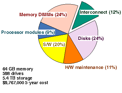
For large systems like these, there is no point in skimping on interconnect -- since the total cost is dominated by commodity processors, memory, disk, and database software.
Starfire sustained over 1,400 MBps of disk bandwidth through Oracle doing the 1 TB TPC-D. This is more delivered disk bandwidth than our previous CS6400 system provided in memory bandwidth. A good scaling rule is that tomorrow's system should deliver more disk bandwidth than today's system provides in memory bandwidth.
Starfire's router-based implementation of the Ultra Port Architecture has extended the Ultra server family bandwidth by a factor of 4x. The error isolation of point-to-point wires has made possible the unique flexibility of Dynamic System Domains, dynamic reconfiguration, and hot swap. The System Service Processor and the use of ECC for both address and data has improved system reliability, availability and serviceability. For more product information on Starfire see [15] [16].
SMP systems like Sun's Ultra servers have a long track record of being simpler to administer and use than NUMA, MPP, and cluster architectures. As SMP implementations continue to scale upwards in power and capacity, the "problem too big" threshold where alternative architectures are needed is also being raised ever higher.
[1] Alan Charlesworth, Andy Phelps, Ricki Williams, Gary Gilbert, "Gigaplane-XB: Extending the Ultra Enterprise Family," Proceedings of Hot Interconnects V, August 22, 1997.
[2] Jack J. Dongarra, Performance of Various Computers Using Standard Linear Equations Software, August 20, 1997, http://performance.netlib.org/performance/html/PERFORM.ps.
[3] John Hennessy and David Patterson. Computer Architecture: a Quantitative Approach, Second Edition, Morgan-Kaufman, San Mateo, CA, 1996, page 374.
[4] John McCalpin, "Memory Bandwidth and Machine Balance in Current High Performance Computers," IEEE TCCA Newsletter, pp. 19-25, December 1995, http://www.computer.org/tab/tcca/news/dec95/dec95_mccalpin.ps.
[5] John McCalpin, Stream: Measuring Sustainable Memory Bandwidth in High Performance Computers. Standard Results as of June 14, 1997, http://www.cs.virginia.edu/stream/.
[6] Larry McVoy and Carl Staelin, "lmbench: Portable Tools for Performance Analysis," Proceedings: USENIX 1996 Annual Technical Conference, January 22-26, 1996, pp. 279-294, http://reality.sgi.com/employees/lm/lmbench/lmbench-usenix.ps.
[7] Kevin Normoyle, Zahir Ebrahim, Bill VanLoo, Satya Nishtala, "The UltraSPARC Port Architecture", Proceedings Hot Interconnects III, August 1995.
[8] Ashok Singhal, David Broniarczyk, Fred Cerauskis, Jeff Price, Leo Yuan, Chris Cheng, Drew Doblar, Steve Fosth, Nalini Agarwal, Kenneth Harvey, Erik Hagersten, "Gigaplane: A High Performance Bus for Large SMPs." Proceedings Hot Interconnects IV, August 1996.
[9] The Standard Performance Evaluation Corporation, SPEC CPU95 Results, Results as of August 29, 1997, http://www.specbench.org/osg/cpu95/results/.
[10] Sun Database Engineering Group, Data Warehousing Performance with SMP and MPP Architectures, July 1997, 40 pages.
[11] Sun Microsystems, The UltraSPARC II Processor Technology, July 1997, 60 pages, http://www.sun.com/ultra30/whitepapers/ultrasparc.pdf.
[12] Sun Microsystems, The Ultra 30 Architecture, July 1997, 62 pages, http://www.sun.com/ultra30/whitepapers/u30.pdf.
[13] Sun Microsystems, The Ultra Enterprise 450 Architecture, August 1997, 30 pages, http://www.sun.com/servers/ultra_enterprise/450/wp/450-arch.pdf.
[14] Sun Microsystems, Ultra Enterprise X000 Server Family: Architecture and Implementation, April 1996, 66 pages, http://www.sun.com/servers/ultra_enterprise/6000/wp.html.
[15] Sun Microsystems, The Ultra Enterprise 10000 Server, January 1997, 35 pages, http://www.sun.com/servers/ultra_enterprise/10000/wp/E10000.pdf.
[16] Sun Microsystems, Ultra Enterprise 10000
Server: SunTrust Reliability, Availability, and Serviceability, January
1997, 36 pages,
http://www.sun.com/servers/ultra_enterprise/10000/wp/suntrust.pdf.
[17] Sun Microsystems, The Sun RSM Array 2000 Architecture, January 1997, 50 pages, http://www.sun.com/servers/datacenter/whitepapers/rsm_arch.pdf.
[18] Transaction Processing Performance Council, Complete Listing of TPC Results Spreadsheet, August 15, 1997, http://www.tpc.org/results/complete_listings/results.pdf.
![]()
(c) 1997 ACM 0-89791-985-8/97/0011 $3.50
Permission to make digital/hard copy of all or part of this work for personal or classroom use is granted without fee provided that copies are not made or distributed for profit or commercial advantage, the copyright notice, the title of the publication and its date appear, and notice is given that copying is by permission of ACM, Inc. To copy otherwise, to republish, to post on servers or to redistribute to lists, requires prior specific permission and/or a fee.
Although the ACM Copyright paragraph is not prominently displayed on PostScript versions -- All individual papers are copyrighted by ACM, with the exception of those produced as work under government contract.